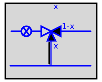
modelThreeWayValveFlow

Information
Hypothesis and equations
Generic flow control model for a secondary hydraulic circuit including a pump.
Bibliography
none
Instructions for use
The input x, between 0 and 1, diverts the flow via 3-way velva. When x is greater than 0.5, it means that the secondary circuit emits too much heat and therefore the sound flow must bereduced. x:=1: no flow in the secondary circuit, everything is redirected to the secondary circuit. x=0: all the flow fixed to the pump is sent to the secondary circuit.
The pump is an all or nothing system which stops when there is no need in the secondary circuit (when x=1.)
Known limits / Use precautions
none
Validations
none
--------------------------------------------------------------
Licensed by EDF under a 3-clause BSD-license
Copyright © EDF 2009 - 2023
BuildSysPro version 3.6.0
Author : Hubert BLERVAQUE, Sila FILFLI, EDF (2011)
--------------------------------------------------------------
Parameters
| Type | Name | Default | Description |
|---|---|---|---|
| Modelica.Units.SI.MassFlowRate | m_flow | 0.01 | Nominal flow rate |
Connectors
| Type | Name | Default | Description |
|---|---|---|---|
| Modelica.Blocks.Interfaces.RealInput[2] | Port1 | Vector including 1-fluid temperature (K), 2-flow rate (kg/s) | |
| Modelica.Blocks.Interfaces.RealInput[2] | Port3 | Vector including 1-fluid temperature (K), 2-flow rate (kg/s) | |
| Modelica.Blocks.Interfaces.RealOutput[2] | Port2 | Vector including 1-fluid temperature (K), 2-flow rate (kg/s) | |
| Modelica.Blocks.Interfaces.RealOutput[2] | Port4 | Vector including 1-fluid temperature (K), 2-flow rate (kg/s) | |
| Modelica.Blocks.Interfaces.RealInput | x | Ratio of valve opening (entre 0 et 1) |
Revisions
Hubert Blervaque 02/2013 : Première implémentation.
Benoît Charrier 05/2015 : Suppression des connecteurs T & m_flow.