modelIntegratedPrimaryLoadSide
Extends from Buildings.Applications.DataCenters.ChillerCooled.Equipment.BaseClasses.PartialIntegratedPrimary.
Information
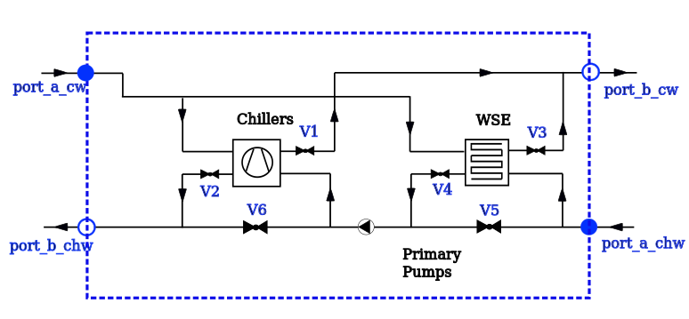
This model implements an integrated water-side economizer (WSE) on the load side of the primary-only chilled water system, as shown in the following figure. In the configuration, users can model multiple chillers with only one integrated WSE.
Implementation
The WSE located on the load side can see the warmest return chilled water, and hence can maximize the use time of the heat exchanger. This system have three operation modes: free cooling (FC) mode, partial mechanical cooling (PMC) mode and fully mechanical cooling (FMC) mode.
There are 7 valves for on/off use only, which can be controlled in order to switch among FC, PMC and FMC mode.
- V1 and V2 are associated with the chiller. When the chiller is commanded to run, V1 and V2 will be open, and vice versa. Note that when the number of chillers are larger than 1, V1 and V2 are vectored models with the same dimension as the chillers.
- V3 and V4 are associated with the WSE. When the WSE is commanded to run, V3 and V4 will be open, and vice versa.
- V5 is for FMC only. When FMC is on, V5 is commanded to on. Otherwise, V5 is off.
- V6 is for FC only. When FC is on, V6 is commanded to on. Otherwise, V6 is off.
- V7 is controlled to track a minimum flowrate through the chiller. If the cooling load is very small (e.g. when the data center start to be occupied), and the flowrate through the chiller is smaller than the minimum requirement, then V7 is open, and the valve position is controlled to meet the minimum flowrate through the chiller. If the cooling load grows, V7 will eventually be fully closed.
The details about how to switch among different cooling modes are shown as:
For Free Cooling (FC) Mode:
- V1 and V2 are closed, and V3 and V4 are open;
- V5 is closed;
- V6 is open;
- V7 is closed;
For Partially Mechanical Cooling (PMC) Mode:
- V1 and V2 are open, and V3 and V4 are open;
- V5 is closed;
- V6 is closed;
- V7 is controlled to track a minumum flowrate through the chiller;
For Fully Mechanical Cooling (FMC) Mode:
- V1 and V2 are open, and V3 and V4 are closed;
- V5 is open;
- V6 is closed;
- V7 is controlled to track a minumum flowrate through the chiller;
Reference
- Stein, Jeff. 2009. Waterside Economizing in Data Centers: Design and Control Considerations.ASHRAE Transactions, 115(2).
Parameters
| Type | Name | Default | Description |
|---|---|---|---|
| Dynamics › Pump | |||
| Modelica.Units.SI.Time | tauPump | 1 | Time constant of fluid volume for nominal flow in pumps, used if energy or mass balance is dynamic |
| Pump | |||
| Integer | numPum | numChi | Number of pumps |
| Buildings.Fluid.Movers.Data.Generic[numPum] | perPum | Performance data for the pumps | |
| Boolean | addPowerToMedium | true | Set to false to avoid any power (=heat and flow work) being added to medium (may give simpler equations) |
| Real | lValPum | 0.0001 | Valve leakage, l=Kv(y=0)/Kv(y=1) |
| Dynamics › Motor speed | |||
| Boolean | use_riseTime | true | Set to true to continuously change motor speed |
| Modelica.Units.SI.Time | riseTime | 30 | Time needed to open or close valve |
| Modelica.Blocks.Types.Init | initPum | initValve | Type of initialization (no init/steady state/initial state/initial output) |
| Real | yPum_start | fill(0, numPum) | Initial value of output:0-closed, 1-fully opened |
| Dynamics › Time needed to open or close valve | |||
| Real | yValPum_start | fill(0, numPum) | Initial value of output:0-closed, 1-fully opened |
Components
| Type | Name | Default | Description |
|---|---|---|---|
| Modelica.Blocks.Interfaces.RealInput[numPum] | yPum | Constant normalized rotational speed | |
| Modelica.Blocks.Interfaces.RealOutput[numPum] | powPum | Electrical power consumed by the pumps | |
| Buildings.Applications.BaseClasses.Equipment.FlowMachine_y | pum | Pumps |
Revisions
-
April 26, 2021, by Kathryn Hinkelman:
Added junctions and removedkFixedredundancies.
See IBPSA, #1472. -
January 12, 2019, by Michael Wetter:
Removed wrong use ofeach. -
July 1, 2017, by Yangyang Fu:
First implementation.