modelFourPipe
Extends from Modelica.Icons.Example.
Information
This model demonstrates the usage of Buildings.Controls.OBC.ASHRAE.G36.FanCoilUnits.Controller, a controller for four-pipe fan coil units based on the sequences defined in ASHRAE Guideline 36, 2021. A generic schematic for such a system is shown below.
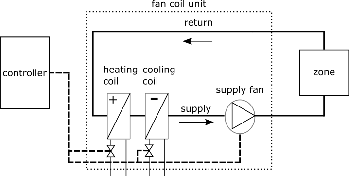
This model consists of
- 3 identical thermal zone models with time-varying internal heat gains and interaction with ambient air through building envelope.
- 3 fan-coil units serving each zone.
- 3 fan coil unit controllers that output the supply fan enable signal and speed signal, the supply air temperature setpoint, the zone air heating and cooling setpoints, and valve positions for heating and cooling coils.
The 3 fan coil units each have a supply fan and a chilled-water cooling coil. The heating coil varies as follows for each instance:
-
fanCoiUnihas no heating coil. -
fanCoiUni1has a hot-water heating coil. -
fanCoiUni2has an electric heating coil.
The HVAC system switches between occupied, unoccupied, unoccupied warm-up and unoccupied pre-cool modes. The cooling coil and heating coil output are modulated to maintain the heating and cooling setpoints. The supply air temperature is modulated based on the differential between the temperature setpoint and the zone temperature to avoid unecessary heating and cooling use and avoid extreme temperature fluctuations.
See the model Buildings.Fluid.ZoneEquipment.FourPipe and Buildings.Controls.OBC.ASHRAE.G36.FanCoilUnits.Controller for a description of the fan coil unit and the controller, respectively.
The thermal zone is a south-facing thermal zone of the medium office building that is also used in Buildings.Examples.VAVReheat, but here only this one room is modeled, and instanciated three times for the three different fan coil units. The external facade is 49.91 meters long, the north-facing interior wall is 40.76 meters, and the room width is 4.58 meters. The room height is 2.74 meters.
Parameters
| Type | Name | Default | Description |
|---|---|---|---|
| Modelica.Units.SI.Length | wSou | 49.91 | Length of south facing exterior wall |
| Modelica.Units.SI.Length | wNor | 40.76 | Lenght of north facing interior wall |
| Modelica.Units.SI.Length | wSid | 6.47 | Length of each of the two side walls |
| Modelica.Units.SI.Length | dRoo | sqrt(wSid^2 - ((wSou - wNor)/2)^2) | Room depth |
| Modelica.Units.SI.Length | hRoo | 2.74 | Room height |
| Modelica.Units.SI.Area | AFlo | (wSou + wNor)/2*dRoo | Floor area |
| Modelica.Units.SI.Volume | VRoo | AFlo*hRoo | Room volume |
| Real | winWalRat | 0.33 | Window to wall ratio for exterior wall |
| Modelica.Units.SI.Length | hWin | 1.5 | Height of windows |
| Real | kInt | 1 | Gain factor to scale internal heat gain in each zone |
| HeatTransfer.Data.Solids.Plywood | matCarTra | Wood for floor | |
| HeatTransfer.Data.Solids.Plywood | matFur | Material for furniture | |
| HeatTransfer.Data.Solids.Concrete | matCon | Concrete | |
| HeatTransfer.Data.Solids.Plywood | matWoo | Wood for exterior construction | |
| HeatTransfer.Data.Solids.GypsumBoard | matGyp | Gypsum board | |
| HeatTransfer.Data.Resistances.Carpet | matCar | Carpet | |
| HeatTransfer.Data.Solids.Generic | matIns | Steelframe construction with insulation | |
| HeatTransfer.Data.Solids.GypsumBoard | matGyp2 | Gypsum board | |
| HeatTransfer.Data.GlazingSystems.DoubleClearAir13Clear | glaSys | Data record for the glazing system | |
| HeatTransfer.Data.OpaqueConstructions.Generic | conExtWal | Exterior construction | |
| HeatTransfer.Data.OpaqueConstructions.Generic | conIntWal | Interior wall construction | |
| HeatTransfer.Data.OpaqueConstructions.Generic | conFur | Construction for internal mass of furniture | |
| HeatTransfer.Data.OpaqueConstructions.Generic | conFlo | Floor construction (opa_a is carpet) |
Components
| Type | Name | Default | Description |
|---|---|---|---|
| Buildings.Fluid.Sources.Boundary_pT | souHea | Source for hot water | |
| Buildings.Fluid.Sources.Boundary_pT | sinHea | Sink for hot water | |
| Buildings.Fluid.Sources.Boundary_pT | sinCoo | Sink for chilled water | |
| Buildings.Fluid.Sources.Boundary_pT | souCoo | Source for chilled water | |
| Buildings.Fluid.ZoneEquipment.FourPipe | fanCoiUni1 | Fan coil unit with no heating coil | |
| Buildings.Controls.OBC.ASHRAE.G36.FanCoilUnits.Controller | conFCU1 | Fan coil unit controller | |
| Buildings.BoundaryConditions.WeatherData.ReaderTMY3 | weaDat | Weather data reader | |
| Buildings.Controls.OBC.ASHRAE.G36.FanCoilUnits.Controller | conFCU2 | Fan coil unit controller | |
| Buildings.Controls.OBC.ASHRAE.G36.FanCoilUnits.Controller | conFCU3 | Fan coil unit controller | |
| MixedAir | zon1 | Zone-1 | |
| Modelica.Thermal.HeatTransfer.Sensors.TemperatureSensor | senTRooAir1 | Air temperature sensor | |
| Modelica.Blocks.Sources.Constant | uSha | Control signal for the shading device | |
| Modelica.Blocks.Routing.Replicator | replicator | ||
| Modelica.Blocks.Sources.CombiTimeTable | intGaiFra | Fraction of internal heat gain | |
| Modelica.Blocks.Math.MatrixGain | gai | Matrix gain to split up heat gain in radiant, convective and latent gain | |
| Modelica.Blocks.Math.Gain[3] | gaiInt | Gain for internal heat gain amplification for each zone | |
| Buildings.Fluid.ZoneEquipment.FourPipe | fanCoiUni2 | Fan coil unit with hot-water heating coil | |
| MixedAir | zon2 | Zone-2 | |
| Modelica.Thermal.HeatTransfer.Sensors.TemperatureSensor | senTRooAir2 | Air temperature sensor | |
| Buildings.Fluid.ZoneEquipment.FourPipe | fanCoiUni3 | Fan coil unit with electric heating coil | |
| MixedAir | zon3 | Zone-3 | |
| Modelica.Thermal.HeatTransfer.Sensors.TemperatureSensor | senTRooAir3 | Air temperature sensor | |
| Buildings.Controls.OBC.CDL.Integers.Sources.Constant | limLev | Cooling and heating demand limit level | |
| Buildings.Controls.SetPoints.OccupancySchedule | occSch | Occupancy schedule | |
| Buildings.Controls.OBC.CDL.Reals.Sources.Constant | TOccHeaSetPoi | Occupied heating temperature setpoint | |
| Buildings.Controls.OBC.CDL.Reals.Sources.Constant | TUnOccCooSet | Unoccupied cooling temperature setpoint | |
| Buildings.Controls.OBC.CDL.Reals.Sources.Constant | TUnOccHeaSet | Unoccupied heating temperature setpoint | |
| Buildings.Controls.OBC.CDL.Reals.GreaterThreshold[3] | greThr | Check if fan speed is above threshold for proven on signal | |
| Buildings.Controls.OBC.CDL.Logical.Timer[3] | tim | Generate fan proven on signal | |
| Buildings.Controls.OBC.CDL.Reals.Sources.Constant | TSetAdj | Unoccupied cooling temperature setpoint | |
| Buildings.Controls.OBC.CDL.Reals.Sources.Constant | cooWarTim | Cooldown and warm-up time | |
| Buildings.Controls.OBC.CDL.Reals.Sources.Constant | TOccCooSetPoi | Occupied cooling temperature setpoint | |
| Modelica.Blocks.Math.Gain[3] | gaiInt1 | Gain for internal heat gain amplification for zone with no heating coil service |
Contents
| Name | Description |
|---|---|
| MediumA | Medium for air |
| MediumW | Medium for hot-water and chilled-water |
| MixedAir | Thermal zone model |
Revisions
-
November 20, 2025, by Karthik Devaprasad:
Updated PI controller parameters on controller instances. Added schematic of generic fan coil unit system integration with controller and thermal zone. -
September 23, 2025, by Cerrina Mouchref, Karthik Devaprasad and Michael Wetter:
First implementation.