modelInjectionTwoWay
Extends from HydronicConfigurations.Interfaces.PartialHydronicConfiguration.
Information
Summary
This circuit (see schematic hereunder) is used for variable flow primary circuits and either constant flow or variable flow consumer circuits. The fixed bypass prevents the primary pressure differential from being transmitted to the consumer circuit. This allows a proper operation of the terminal control valves on the consumer side when the primary pressure differential is either too low or too high or varying too much. For variable flow consumer circuits, the supply temperature set point must be different from the primary circuit.
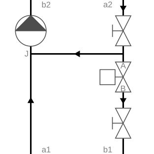
The following table presents the main characteristics of this configuration.
| Primary circuit |
Variable flow (See caveats in Buildings.Fluid.HydronicConfigurations.ActiveNetworks.Examples.InjectionTwoWayConstant: control options are critical to achieve a truly variable flow.) |
| Secondary (consumer) circuit | Constant or variable flow |
| Typical applications |
Consumer circuit supply temperature set point different from primary circuit (Otherwise use Buildings.Fluid.HydronicConfigurations.ActiveNetworks.Decoupling) Primary pressure differential either too low or too high or varying too much such as in DHC systems |
| Non-recommended applications |
Variable flow consumer circuit with same supply temperature set point as primary circuit, see
Buildings.Fluid.HydronicConfigurations.ActiveNetworks.Examples.InjectionTwoWayVariable Variable flow consumer circuit with return temperature control, see Buildings.Fluid.HydronicConfigurations.ActiveNetworks.Examples.InjectionTwoWayVariableReturn |
| Built-in valve control options |
Supply temperature (must be different from primary) Return temperature (incompatible with variable secondary) |
|
Control valve selection (See the nomenclature in the schematic.) |
β = ΔpA-B / Δp1 The valve is sized with a pressure drop of Δp1 / 2 which yields an authority of 0.5. |
| Balancing requirement |
dpBal1_nominal=dp1_nominal-dpValve_nominal
for the primary design flow rate
ṁ1, design = ṁ2, design *
(T2, sup, design - T2, ret, design) /
(T1, sup, design - T2, ret, design)
|
|
Lumped flow resistance includes (With the setting use_lumFloRes=true.)
|
Control valve val and primary balancing valve res1
|
Additional comments
The pressure drop through the control valve is compensated by the primary pump, reducing the secondary pump head.
Components
| Type | Name | Default | Description |
|---|---|---|---|
| FixedResistances.Junction | junSup | Junction | |
| Components.Pump | pum | Pump | |
| Components.TwoWayValve | val | Control valve | |
| Sensors.TemperatureTwoPort | T2Sup | Consumer circuit supply temperature sensor | |
| FixedResistances.Junction | junRet | Junction | |
| FixedResistances.PressureDrop | res2 | Secondary balancing valve | |
| FixedResistances.PressureDrop | res1 | Primary balancing valve | |
| Sensors.TemperatureTwoPort | T2Ret | Consumer circuit return temperature sensor | |
| Controls.PIDWithOperatingMode | ctl | Controller | |
| Buildings.Controls.OBC.CDL.Integers.GreaterThreshold | isEna | Returns true if enabled | |
| Buildings.Controls.OBC.CDL.Routing.RealExtractor | extIndSig | Select measured signal | |
| FixedResistances.LosslessPipe | res3 | Fluid pass-through that can be replaced by check valve | |
| Buildings.Controls.OBC.CDL.Integers.Sources.Constant | ctlVar | Controlled variable selector |
Revisions
-
June 30, 2022, by Antoine Gautier:
First implementation.