modelChillerBorefield
ETS model for 5GDHC systems with heat recovery chiller and optional borefield
Extends from Buildings.Obsolete.DHC.ETS.Combined.BaseClasses.PartialParallel.
Information
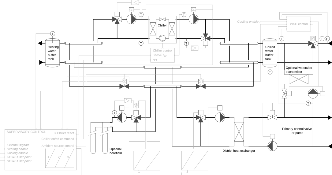
This model represents an energy transfer station as illustrated in the schematics below.
- The heating and cooling functions are provided by a heat recovery chiller, see Buildings.Obsolete.DHC.ETS.Combined.Subsystems.Chiller for the operating principles and modeling assumptions. The condenser and evaporator loops are equipped with constant speed pumps.
- The supervisory controller ensures the load balancing between the condenser side and the evaporator side of the chiller by controlling in sequence an optional geothermal borefield (priority system), the district heat exchanger (second priority system), and ultimately the chiller, by resetting down the chilled water supply temperature, see Buildings.Obsolete.DHC.ETS.Combined.Controls.Supervisory for a detailed description. The borefield and district heat exchanger loops are equipped with variable speed pumps modulated by the supervisory controller.
Note that the heating and cooling enable signals (uHea and uCoo)
connected to this model should be switched to false when the
building has no corresponding demand (e.g., based on the requests yielded by
the terminal unit controllers, in conjunction with a schedule).
This will significantly improve the system performance as it is a
necessary condition for the chiller to be operated at a lower lift, see
Buildings.DHC.ETS.Combined.Controls.Reset.
Parameters
| Type | Name | Default | Description |
|---|---|---|---|
| Boolean | have_borFie | false | Set to true in case a borefield is used in addition of the district HX |
| Boolean | have_WSE | false | Set to true in case a waterside economizer is used |
| Buildings.Fluid.Geothermal.Borefields.Data.Borefield.Example | datBorFie | ||
| Chiller | |||
| Modelica.Units.SI.PressureDifference | dpCon_nominal | Nominal pressure drop accross condenser | |
| Modelica.Units.SI.PressureDifference | dpEva_nominal | Nominal pressure drop accross evaporator | |
| Buildings.Fluid.Chillers.Data.ElectricEIR.Generic | datChi | Chiller performance data | |
| Waterside economizer | |||
| Modelica.Units.SI.PressureDifference | dp1WSE_nominal | 40E3 | Nominal pressure drop across heat exchanger on district side |
| Modelica.Units.SI.PressureDifference | dp2WSE_nominal | 40E3 | Nominal pressure drop across heat exchanger on building side |
| Modelica.Units.SI.HeatFlowRate | QWSE_flow_nominal | 0 | Nominal heat flow rate through heat exchanger (<=0) |
| Modelica.Units.SI.Temperature | T_a1WSE_nominal | 279.15 | Nominal water inlet temperature on district side |
| Modelica.Units.SI.Temperature | T_b1WSE_nominal | 284.15 | Nominal water outlet temperature on district side |
| Modelica.Units.SI.Temperature | T_a2WSE_nominal | 288.15 | Nominal water inlet temperature on building side |
| Modelica.Units.SI.Temperature | T_b2WSE_nominal | 281.15 | Nominal water outlet temperature on building side |
| Real | y1WSEMin | 0.05 | Minimum pump flow rate or valve opening for temperature measurement (fractional) |
| Modelica.Units.SI.MassFlowRate | m1WSE_flow_nominal | abs(QWSE_flow_nominal/4200/(T_b1WSE_nominal - T_a1WSE_nominal)) | WSE primary mass flow rate |
| Borefield | |||
| Modelica.Units.SI.Temperature | TBorWatEntMax | 313.15 | Maximum value of borefield water entering temperature |
| Real | spePumBorMin | 0.1 | Borefield pump minimum speed |
| Modelica.Units.SI.Pressure | dpBorFie_nominal | 5E4 | Pressure losses for the entire borefield (control valve excluded) |
| Supervisory controller | |||
| Buildings.Controls.OBC.CDL.Types.SimpleController | controllerType | Buildings.Controls.OBC.CDL.Types.SimpleController.PI | Type of controller |
| Real | kHot | 0.05 | Gain of controller on hot side |
| Real | kCol | 0.1 | Gain of controller on cold side |
| Modelica.Units.SI.Time | TiHot | 300 | Time constant of integrator block on hot side |
| Modelica.Units.SI.Time | TiCol | 120 | Time constant of integrator block on cold side |
| Modelica.Units.SI.Temperature | THeaWatSupSetMin | datChi.TConEntMin + 5 | Minimum value of heating water supply temperature set point |
| Modelica.Units.SI.Temperature | TChiWatSupSetMin | datChi.TEvaLvgMin | Minimum value of chilled water supply temperature set point |
| Modelica.Units.SI.Temperature | TChiWatSupSetMax | datChi.TEvaLvgMax | Minimum value of chilled water supply temperature set point |
Components
| Type | Name | Default | Description |
|---|---|---|---|
| Buildings.Obsolete.DHC.ETS.Combined.Subsystems.Chiller | chi | Chiller | |
| Buildings.Obsolete.DHC.ETS.Combined.Subsystems.Borefield | borFie | Borefield | |
| Buildings.Controls.OBC.CDL.Reals.Sources.Constant | zerPPum | Zero power | |
| Buildings.Controls.OBC.CDL.Reals.Sources.Constant | zerPHea | Zero power | |
| Buildings.DHC.Networks.BaseClasses.DifferenceEnthalpyFlowRate | dHFloHeaWat | Variation of enthalpy flow rate | |
| Buildings.Controls.OBC.CDL.Interfaces.RealOutput | dHHeaWat_flow | Heating water distributed energy flow rate | |
| Buildings.Controls.OBC.CDL.Interfaces.RealOutput | dHChiWat_flow | Chilled water distributed energy flow rate | |
| Buildings.DHC.Networks.BaseClasses.DifferenceEnthalpyFlowRate | dHFloChiWat | Variation of enthalpy flow rate | |
| Buildings.DHC.ETS.Combined.Subsystems.WatersideEconomizer | WSE | Waterside economizer | |
| Buildings.DHC.ETS.BaseClasses.Junction | splWSE | Flow splitter for WSE | |
| Buildings.DHC.ETS.BaseClasses.Junction | mixWSE | Flow mixer for WSE |
Revisions
-
November 3, 2025, by Michael Wetter:
Moved toBuildings.Obsolete.
This is for #4354. -
March 6, 2025, by Hongxiang Fu:
Added parameters to support chilled water temperature reset.
This is for #4133. -
November 22, 2024, by Michael Wetter:
Reduced number of time events by replacing zero order hold with true and false hold, and increasing the minimum cycle time.
This is for #4058. -
March 27, 2024, by David Blum:
Update icon.
This is for issue #3606. -
April 30, 2021, by Michael Wetter:
Reformulated replaceable class to avoid access of components that are not in the constraining type.
This is for issue #2471. -
July 31, 2020, by Antoine Gautier:
First implementation.