modelAirToWater
Extends from Buildings.Templates.Plants.HeatPumps.Interfaces.PartialHeatPumpPlant.
Information
Description
This template represents an air-to-water heat pump plant
with closed-loop controls. While the heat pump plant configuration can be changed
through parameters, the image below shows a typical configuration with
two reversible air-to-water heat pumps, a primary-secondary distribution system
and a sidestream heat recovery chiller.
For a detailed schematic of the actual plant configuration, refer to the diagram
view of the plant component. In Dymola, for example, you can access this by right-clicking
the component pla in the model
Buildings.Templates.Plants.HeatPumps.Validation.AirToWater
and selecting "Show Component" from the context menu.
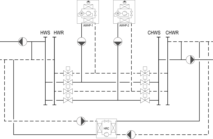
Currently, only identical heat pumps are supported. Although the template can accommodate any number of identical heat pumps, the graphical feedback for system configuration via the diagram layer is only accurate for up to 6 devices.
The supported plant configurations are enumerated in the table below.
The first option displayed in bold characters corresponds to the default
configuration.
| Configuration parameter | Options | Notes |
|---|---|---|
| Function |
Heating and cooling Heating-only |
The plant always provides heating hot water. Setting the parameter have_chiWat to true (default setting) allows
modeling a plant that provides both heating hot water and chilled water.
|
| Heat recovery |
Without sidestream heat recovery chiller With sidestream heat recovery chiller |
This option is only available for heating and cooling plants. When selected, the template includes a chiller and its associated dedicated primary CHW and CW pumps. The chiller is considered connected in a sidestream configuration to both the CHW return and the HW return. |
| Type of distribution |
Constant primary-variable secondary centralized Variable primary-only |
It is assumed that the HW and the CHW loops have the
same type of distribution, as specified by this parameter. Most AWHPs on the market use a reverse cycle for defrosting. This requires maximum primary flow during defrost cycles. Consequently, variable primary plants commonly adopt a high minimum flow setpoint, typically close to the design flow rate, effectively operating akin to constant primary plants but with variable speed pumps controlling the loop differential pressure. While the flow rate directed towards the loads varies, the bypass valve control loop ensures a constant primary flow for a given number of staged units. "Centralized secondary pumps" refers to configurations with a single group of secondary pumps that is typically integrated into the plant. Distributed secondary pumps with multiple secondary loops served by dedicated secondary pumps are currently not supported. |
| Type of primary pump arrangement |
Dedicated Headered |
It is assumed that the HW and the CHW loops have the same type of primary pump arrangement, as specified by this parameter. |
| Separate dedicated primary CHW pumps |
False True |
This option is only available for heating and cooling plants with dedicated primary pumps. If this option is not selected (default setting), each AWHP uses a common dedicated primary pump for HW and CHW – this pump is then denoted as the primary HW pump. Otherwise, each AWHP relies on a separate dedicated HW pump and a separate dedicated CHW pump. |
| Type of primary HW pumps |
Variable speed Constant speed |
For constant primary-variable secondary distributions, the variable speed primary pumps are commanded at fixed speeds, determined during the Testing, Adjusting and Balancing phase to provide design AWHP flow in heating and cooling modes. The same intent is achieved with constant speed primary pumps through the use of balancing valves. |
| Type of primary CHW pumps |
Variable speed Constant speed |
See the note above on primary HW pumps. |
| HW buffer tank |
HW buffer tank in the primary supply HW buffer tank in the primary return No HW buffer tank |
By default, the HW buffer tank is considered integrated into the primary supply to mitigate the impact of defrost cycles on the temperature of the HW supplied to the loads. This assumes that the buffer tank is well-mixed. The default sizing of the tank corresponds to 4 min of the design primary flow rate. This is based on manufacturer recommendations, which account for the fact that defrost cycles can take 3 to 5 min to complete. |
| CHW buffer tank |
CHW buffer tank in the primary return CHW buffer tank in the primary supply No CHW buffer tank |
By default, the CHW buffer tank is considered integrated into the primary return to mitigate the impact of rapid load variations on the plant controls. This assumes that the buffer tank is well-mixed. The default sizing of the tank corresponds to 2 min of the design primary flow rate, based on manufacturer recommendations. |
| Controller |
Closed-loop controls with supply temperature and differential pressure reset |
Most parts of the sequence of operation are similar to that
described in ASHRAE, 2021 for chiller plants. See the documentation of Buildings.Templates.Plants.Controls.HeatPumps.AirToWater for more details. An open loop controller is also available for validation purposes. |
Control points
The control sequence implemented in this template requires the external input points specified in the documentation of the controller Buildings.Templates.Plants.HeatPumps.Components.Controls.AirToWater.
Implementation details
The pressure drops of the heat pump CHW and HW heat exchangers are calculated
within the isolation valve component valIso based on lumped flow
coefficients for the sake of computational efficiency.
The template uses a heat pump model that interpolates capacity and power
from manufacturer data along the CHW/HW temperature, the outdoor
air temperature and the part load ratio.
The heat pump performance data are provided via the subrecords
dat.hp.perHeaHp and dat.hp.perCooHp for the
heating mode and the cooling mode, respectively.
For the required format of the performance data files,
please refer to the documentation of the block
Buildings.Fluid.HeatPumps.ModularReversible.RefrigerantCycle.BaseClasses.TableData2DLoadDep.
References
- ASHRAE, 2021. Guideline 36-2021, High-Performance Sequences of Operation for HVAC Systems. Atlanta, GA.
Parameters
| Type | Name | Default | Description |
|---|---|---|---|
| Modelica.Units.SI.PressureDifference | dpValCheHeaWat_nominal | dat.dpValCheHeaWat_nominal*(hp.mHeaWatHp_flow_nominal/max(dat.pumHeaWatPri.m_flow_nominal))^2 | Primary HW pump check valve pressure drop at design HW flow rate |
| Modelica.Units.SI.PressureDifference | dpValCheChiWat_nominal | if have_chiWat then (if typPumChiWatPri == Buildings.Templates.Plants.HeatPumps.Types.PumpsPrimary.None then dat.dpValCheHeaWat_nominal*(hp.mChiWatHp_flow_nominal/max(dat.pumHeaWatPri.m_flow_nominal))^2 else dat.dpValCheChiWat_nominal) else 0 | Primary (CHW or common HW and CHW) pump check valve pressure drop at design CHW flow rate |
| Modelica.Units.SI.PressureDifference | dpBalHeaWatHp_nominal | if is_dpBalYPumSetCal and typPumHeaWatPri == Buildings.Templates.Plants.HeatPumps.Types.PumpsPrimary.Constant then Buildings.Templates.Utilities.computeBalancingPressureDrop(m_flow_nominal = hp.mHeaWatHp_flow_nominal, dp_nominal = hp.dpHeaWatHp_nominal + max(valIso.dpValveHeaWat_nominal)*((if have_valHpInlIso then 1 else 0) + (if have_valHpOutIso then 1 else 0)) + dpValCheHeaWat_nominal, datPum = dat.pumHeaWatPriSin[1]) else dat.dpBalHeaWatHp_nominal | HP HW balancing valve pressure drop at design HW flow |
| Modelica.Units.SI.PressureDifference | dpBalChiWatHp_nominal | if is_dpBalYPumSetCal and (typPumChiWatPri == Buildings.Templates.Plants.HeatPumps.Types.PumpsPrimary.Constant or have_chiWat and not have_pumChiWatPriDed and typPumHeaWatPri == Buildings.Templates.Plants.HeatPumps.Types.PumpsPrimary.Constant) then Buildings.Templates.Utilities.computeBalancingPressureDrop(m_flow_nominal = hp.mChiWatHp_flow_nominal, dp_nominal = hp.dpChiWatHp_nominal + max(valIso.dpValveChiWat_nominal)*((if have_valHpInlIso then 1 else 0) + (if have_valHpOutIso then 1 else 0)) + dpValCheChiWat_nominal, datPum = if cfg.typPumChiWatPri == Buildings.Templates.Plants.HeatPumps.Types.PumpsPrimary.Constant then dat.pumChiWatPriSin[1] else dat.pumHeaWatPriSin[1]) else dat.dpBalChiWatHp_nominal | HP CHW balancing valve pressure drop at design CHW flow |
| Advanced | |||
| Boolean | is_dpBalYPumSetCal | false | Set to true to automatically size balancing valves or evaluate pump speed providing design flow |
| Information provided by testing, adjusting, and balancing contractor | |||
| Real | yPumHeaWatPriSet | Primary pump speed providing design heat pump flow in heating mode | |
| Real | yPumChiWatPriSet | Primary pump speed providing design heat pump flow in cooling mode | |
Components
| Type | Name | Default | Description |
|---|---|---|---|
| Buildings.Templates.Plants.HeatPumps.Components.HeatPumpGroups.AirToWater | hp | Heat pump group | |
| Components.PumpsPrimaryDedicated | pumPri | Dedicated primary pumps | |
| Components.ValvesIsolation | valIso | Heat pump isolation valves | |
| Buildings.Templates.Components.Pumps.Multiple | pumChiWatPri | Headered primary CHW pumps | |
| Buildings.Templates.Components.Routing.SingleToMultiple | inlPumChiWatPri | Primary CHW pumps inlet manifold | |
| Buildings.Templates.Components.Routing.MultipleToSingle | outPumChiWatPri | Primary CHW pumps outlet manifold | |
| Buildings.Templates.Components.Routing.PassThroughFluid | supChiWatPri | Primary CHW supply pipe - Plant with dedicated primary CHW pumps | |
| Buildings.Templates.Components.Sensors.VolumeFlowRate | VChiWatPri_flow | Primary CHW volume flow rate | |
| Buildings.Templates.Components.Routing.Junction | junChiWatBypSup | Fluid junction | |
| Buildings.Templates.Components.Sensors.Temperature | TChiWatPriSup | Primary CHW supply temperature | |
| Buildings.Templates.Components.Routing.Junction | junChiWatBypRet | Fluid junction | |
| Buildings.Templates.Components.Sensors.Temperature | TChiWatPriRet | Primary CHW return temperature | |
| Buildings.Templates.Components.Actuators.Valve | valChiWatMinByp | CHW minimum flow bypass valve or fixed bypass depending on type of distribution | |
| Buildings.Templates.Components.Tanks.Buffer | tanChiWatSup | CHW buffer tank | |
| Buildings.Templates.Components.Tanks.Buffer | tanChiWatRet | CHW buffer tank | |
| Buildings.Templates.Components.Pumps.Multiple | pumChiWatSec | Secondary CHW pumps | |
| Buildings.Templates.Components.Routing.SingleToMultiple | inlPumChiWatSec | Secondary CHW pumps inlet manifold | |
| Buildings.Templates.Components.Routing.MultipleToSingle | outPumChiWatSec | Secondary CHW pumps outlet manifold | |
| Buildings.Templates.Components.Routing.PassThroughFluid | supChiWatSec | Secondary CHW supply pipe - Plant without secondary CHW pumps | |
| Buildings.Templates.Components.Sensors.VolumeFlowRate | VChiWatSec_flow | Secondary CHW volume flow rate | |
| Buildings.Templates.Components.Sensors.Temperature | TChiWatSecSup | Secondary CHW supply temperature | |
| Buildings.Templates.Components.Sensors.Temperature | TChiWatSecRet | Secondary CHW return temperature | |
| Buildings.Templates.Components.Sensors.DifferentialPressure | dpChiWatLoc | Local CHW ∆p sensor | |
| Buildings.Templates.Components.Routing.SingleToMultiple | inlPumHeaWatPri | Primary HW pumps inlet manifold | |
| Buildings.Templates.Components.Pumps.Multiple | pumHeaWatPri | Headered primary HW pumps | |
| Buildings.Templates.Components.Routing.MultipleToSingle | outPumHeaWatPri | Primary HW pumps outlet manifold | |
| Buildings.Templates.Components.Routing.PassThroughFluid | supHeaWatPri | Primary HW supply pipe - Plant with dedicated primary HW pumps | |
| Buildings.Templates.Components.Sensors.VolumeFlowRate | VHeaWatPri_flow | Primary HW volume flow rate | |
| Buildings.Templates.Components.Routing.Junction | junHeaWatBypSup | Fluid junction | |
| Buildings.Templates.Components.Sensors.Temperature | THeaWatPriSup | Primary HW supply temperature | |
| Buildings.Templates.Components.Sensors.Temperature | THeaWatPriRet | Primary HW return temperature | |
| Buildings.Templates.Components.Routing.Junction | junHeaWatBypRet | Fluid junction | |
| Buildings.Templates.Components.Actuators.Valve | valHeaWatMinByp | HW minimum flow bypass valve or fixed bypass depending on type of distribution | |
| Buildings.Templates.Components.Tanks.Buffer | tanHeaWatSup | HW buffer tank | |
| Buildings.Templates.Components.Tanks.Buffer | tanHeaWatRet | HW buffer tank | |
| Buildings.Templates.Components.Pumps.Multiple | pumHeaWatSec | Secondary HW pumps | |
| Buildings.Templates.Components.Routing.SingleToMultiple | inlPumHeaWatSec | Secondary HW pumps inlet manifold | |
| Buildings.Templates.Components.Routing.MultipleToSingle | outPumHeaWatSec | Secondary HW pumps outlet manifold | |
| Buildings.Templates.Components.Routing.PassThroughFluid | supHeaWatSec | Secondary HW supply pipe - Plant without secondary HW pumps | |
| Buildings.Templates.Components.Sensors.VolumeFlowRate | VHeaWatSec_flow | Secondary HW volume flow rate | |
| Buildings.Templates.Components.Sensors.Temperature | THeaWatSecSup | Secondary HW supply temperature | |
| Buildings.Templates.Components.Sensors.Temperature | THeaWatSecRet | Secondary HW return temperature | |
| Buildings.Templates.Components.Sensors.DifferentialPressure | dpHeaWatLoc | Local HW ∆p sensor | |
| Components.HeatRecoveryChiller | hrc | Sidestream heat recovery chiller | |
| Buildings.Templates.Components.Routing.Junction | junHeaWatHrcEnt | Fluid junction | |
| Buildings.Templates.Components.Routing.Junction | junHeaWatHrcLvg | Fluid junction | |
| Buildings.Templates.Components.Routing.Junction | junChiWatHrcEnt | Fluid junction | |
| Buildings.Templates.Components.Routing.Junction | junChiWatHrcLvg | Fluid junction | |
| Buildings.Templates.Components.Sensors.Temperature | TChiWatRetUpsHrc | CHW return temperature upstream of HRC | |
| Buildings.Templates.Components.Sensors.Temperature | THeaWatRetUpsHrc | HW return temperature upstream of HRC | |
| Fluid.Sources.Boundary_pT | bouHeaWat | Pressure boundary condition mimicking expansion tank |
Revisions
-
March 23, 2026, by Antoine Gautier:
Refactored HP and HRC components with two separate connectors for HW and CHW supply temperature setpoints.
This is for #4507. -
August 21, 2025, by Antoine Gautier:
Refactored with load-dependent 2D table data heat pump model.
This is for #4152. -
May 31, 2024, by Antoine Gautier:
Added sidestream heat recovery chiller, primary-only pumping, buffer tanks, failsafe staging conditions and internal computation of pump speed or balancing valve ∆p to meet design flow.
This is for #3808. -
March 29, 2024, by Antoine Gautier:
First implementation.