modelCloset
Extends from Buildings.ThermalZones.Detailed.MixedAir.
Information
This is a model for the closet attached to test cell 3A in the LBNL User Facility. This documentation describes the wall constructions used in the closet. Documentation describing how it should be connected to other models in the package to form a complete model of test cell X3A can be found in Buildings.ThermalZones.Detailed.FLEXLAB.Rooms.X3A.
There are four different wall sections connected to the closet modeled here. They are shown in the figure below.
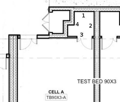
The different wall sections are represented in the model according to the following table.
| Wall Section Number | Description | Location in Model | Corresponding Layer |
|---|---|---|---|
| 1 | North wall on the exterior of the buildings | datConExt[1] | higIns |
| 2 | East wall connected to ThermalZones.Detailed.FLEXLAB.Rooms.X3B.Closet | datConBou[2] | celDiv |
| 3 | Air space connected to partition wall and door in TestCell model | Wall: datSurBou[1] Door: datSurBou[2] |
|
| 4 | West wall connected to Electrical | datConBou[1] | higIns |
There are two additional surfaces which are not included in the diagram. One is the model of the roof. It is
modeled in datConExt[2] using the layer roo. The other is the floor, which is modeled in
datConBou[1] using the layer slaCon.
Several of the connections in this model are intended to be connected to specific surfaces in other room models. The following table describes the connections to models outside of the X3A package.. The connections in datConExt are not described in the table because they are connected to the external environment, and no additional heat port connections are necessary. A rationale for why the model is created this way is also provided if it is considered necessary.
| Location in Closet | Description of External Connection | Location in External Model | Rationale |
|---|---|---|---|
| surf_conBou[2] | X3B.Closet | References a data table | A data table is used, instead of a model of ThermalZones.Detailed.FLEXLAB.Rooms.X3B.Closet, because the goal of this model is to be able to perform simulations of TestCell with minimal complexity, by simplifying the neighboring test cells. The wall separating the test cells is highly insulated, and it is believed that the error in simulations caused by using a data table will be negligible. |
| surf_conBou[3] | Ground temperature | There is no specific connection which is appropriate connection for this construction. surf_conBou[3] represents the floor of the room, and must be connected to a heat port representing the ground temperature. |
Parameters
| Type | Name | Default | Description |
|---|---|---|---|
| Data.Constructions.OpaqueConstructions.DividingWalls.CellAndElectricalDividingWall | higIns | High insulation wall. Between X3A closet and exterior, X3A closet and electrical room | |
| Data.Constructions.OpaqueConstructions.DividingWalls.TestCellDividngWall | celDiv | Wall dividing the X3A closet and the X3B closet | |
| Data.Constructions.OpaqueConstructions.Roofs.ASHRAE_901_2010Roof | roo | Construction of the roof of the closet in X3A | |
| HeatTransfer.Data.OpaqueConstructions.Generic | slaCon | Construction of the slab |
Revisions
- Sept 16, 2013 by Peter Grant:
Added a model representing the floor. - July 26, 2013 by Peter Grant:
First implementation.