
modelPlateHEXvle2vle_L3_2ph_ntu
VLE 2 VLE | L2 | PlateHEX NTU
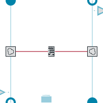
Extends from ClaRa.Basics.Icons.HEX01Plate.
Information
For detailed model documentation please consult the html-documentation shipped with ClaRa.
Authorship and Copyright Statement for original (initial) Contribution
Author:
ClaRa development team, Copyright © 2017 - 2022.References:
For references please consult the html-documentation shipped with ClaRa.
Remarks:
This component was developed for ClaRa library.
Acknowledgements:
CLA:
Parameters
| Type | Name | Default | Description |
|---|---|---|---|
| Boolean | showExpertSummary | simCenter.showExpertSummary | |Summary and Visualisation||True, if expert summary should be applied |
| Boolean | showData | true | |Summary and Visualisation||True, if a data port containing p,T,h,s,m_flow shall be shown, else false |
| General › Fundamental Definitions | |||
| TILMedia.VLEFluid.Types.BaseVLEFluid | medium_a | simCenter.fluid1 | Medium to be used for flow 1 |
| TILMedia.VLEFluid.Types.BaseVLEFluid | medium_b | simCenter.fluid1 | Medium to be used for flow 2 |
| General › Geometry | |||
| ClaRa.Basics.Units.Length | width | 1 | Plate width |
| ClaRa.Basics.Units.Length | length | 1 | Plate length |
| ClaRa.Basics.Units.Length | thickness_wall | 0.01 | Wall thickness of the plate |
| Integer | N_plates | 4 | Number of tubes in parallel |
| ClaRa.Basics.Units.Length | amp | 0.001 | Amplitude of corrugated plate |
| ClaRa.Basics.Units.Length | length_wave | 2*Modelica.Constants.pi*amp | Wave length of corrugated plate |
| ClaRa.Basics.Units.Angle | phi | 60*Modelica.Constants.pi/180 | Corrugation angle |
| ClaRa.Basics.Units.Length | z_in_a | length/2 | Inlet position from bottom for flow_a |
| ClaRa.Basics.Units.Length | z_out_a | length/2 | Outlet position from bottom for flow_a |
| ClaRa.Basics.Units.Length | z_in_b | length/2 | Inlet position from bottom for flow_b |
| ClaRa.Basics.Units.Length | z_out_b | length/2 | Outlet position from bottom for flow_b |
| Real[2] | CF_geo | ones(2) | Correction factor for heat transfer area dedicated to surfuca of: 1|flow_a 2|flow_b |
| Flow_a › Fundamental Definitions | |||
| Boolean | frictionAtInlet_a | false | True if pressure loss between first cell and inlet shall be considered |
| Boolean | frictionAtOutlet_a | false | True if pressure loss between last cell and outlet shall be considered |
| Flow_a › Nominal Values Flow_a | |||
| SI.MassFlowRate | m_nom_a | 1 | Nominal mass flow on A side |
| SI.Pressure | p_nom_a | 1e5 | Nominal pressure on A side |
| SI.EnthalpyMassSpecific | h_nom_a | 85e3 | Nominal specific enthalpy on A side |
| SI.Pressure | Delta_p_nom_a | 1000 | Nominal pressure loss on A side |
| Flow_b › Nominal Values Flow_b | |||
| SI.MassFlowRate | m_nom_b | 1 | Nominal mass flow on tube side |
| SI.Pressure | p_nom_b | 1e5 | Nominal pressure on tube side |
| SI.EnthalpyMassSpecific | h_nom_b | 85e3 | Nominal specific enthalpy on tube side |
| SI.Pressure | Delta_p_nom_b | 1000 | Nominal pressure loss on tube side |
| Flow_b › Fundamental Definitions | |||
| Boolean | frictionAtInlet_b | false | True if pressure loss between first cell and inlet shall be considered |
| Boolean | frictionAtOutlet_b | false | True if pressure loss between last cell and outlet shall be considered |
| Wall › Fundamental Definitions | |||
| SI.Mass | mass_struc | 0 | Additional to mass of the plate HX calculated by density*length*width*thicknesswall |
| Initialisation | |||
| Boolean | useHomotopy | simCenter.useHomotopy | true, if homotopy method is used during initialisation |
| Initialisation › Flow_a | |||
| Integer | initOption_a | 0 | Type of initialisation |
| SI.EnthalpyMassSpecific | h_start_a | 85e3 | Start value of sytsem specific enthalpy |
| SI.Pressure | p_start_a | 1e5 | Start value of sytsem pressure |
| SI.MassFraction[medium_a.nc - 1] | xi_start_a | zeros(medium_a.nc - 1) | Initial composition for flow_a |
| Initialisation › Flow_b | |||
| Integer | initOption_b | 0 | Type of initialisation |
| SI.EnthalpyMassSpecific | h_start_b | 85e3 | Start value of sytsem specific enthalpy |
| SI.Pressure | p_start_b | 1e5 | Start value of sytsem pressure |
| SI.MassFraction[medium_b.nc - 1] | xi_start_b | zeros(medium_b.nc - 1) | Initial composition for flow_b |
| Initialisation › Wall | |||
| Integer | initOptionWall | 0 | |Initialisation option for wall |
| SI.Temperature[3] | T_w_a_start | ones(3)*293.15 | Initial wall temperature flow_a side |
| SI.Temperature[3] | T_w_b_start | ones(3)*293.15 | Initial wall temperature flow_b side |
| Integer | initOption_yps | 3 | Volumetric initialisation |
| Real[2] | yps_start | {0.33, 0.33} | Initial area fraction 1phase | 2phase |
| Expert Settings › NTU model | |||
| Real | gain_eff | 1 | Avoid effectiveness > 1, high gain_eff leads to stricter observation but may cause numeric errors |
| ClaRa.Basics.Units.Time | Tau_stab | 0.1 | Time constant for numeric stabilisation w.r.t. heat flow rates |
Connectors
| Type | Name | Default | Description |
|---|---|---|---|
| ClaRa.Basics.Interfaces.FluidPortIn | In_b | ||
| ClaRa.Basics.Interfaces.FluidPortOut | Out_b | ||
| ClaRa.Basics.Interfaces.FluidPortOut | Out_a | ||
| ClaRa.Basics.Interfaces.FluidPortIn | In_a | ||
| ClaRa.Basics.Interfaces.EyeOut | eye2 | ||
| ClaRa.Basics.Interfaces.EyeOut | eye1 |
Components
| Type | Name | Default | Description |
|---|---|---|---|
| ClaRa.SimCenter | simCenter | ||
| ClaRa.Basics.ControlVolumes.FluidVolumes.VolumeVLE_L2 | flow_a | ||
| ClaRa.Basics.ControlVolumes.FluidVolumes.VolumeVLE_L2 | flow_b | ||
| ClaRa.Basics.ControlVolumes.SolidVolumes.NTU_plate_L3_standalone | thinWall | ||
| Summary | summary |
Contents
| Name | Description |
|---|---|
 Outline Outline | |
 Summary Summary | |
 HeatExchangerType HeatExchangerType | |
 HeatTransferInner_a HeatTransferInner_a | |
 PressureLoss_a PressureLoss_a | |
| HeatTransferInner_b | |
| PressureLoss_b | |
 WallMaterial WallMaterial | |
| HeatCapacityAveraging |
Revisions
For revisions please consult the html-documentation shipped with ClaRa.