
modelIEEE14CLA
IEEE 14-bus system benchmark formed with 14 buses, 5 generators (2 generators and 3 synchronous condensers), 1 shunt, 3 transformers , 17 lines and 11 loads. At t=50s, the consumption of load 5 increases. Three Current Limit Automatons are supervising current on lines B1-B5, B1-B2 and B2-B5.
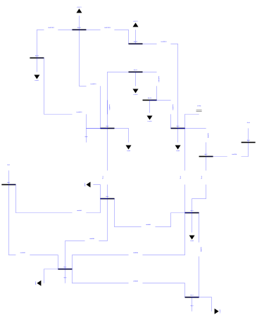
Extends from Dynawo.Examples.IEEE14.BaseClasses.IEEE14Base (Base class for IEEE 14-bus system benchmark formed with 14 buses, 5 generators (2 generators and 3 synchronous condensers), 1 shunt, 3 transformers , 17 lines and 11 loads.), Modelica.Icons.Example (Icon for runnable examples).
Information
The purpose of the current limit automatons is to disconnect the monitored component when the current is higher than a predefined threshold during a certain amount of time.
At t =50s, the active power consumption of load 5 increases by 0.3 pu. Thus, the current on the lines increases. For LineB1B2 and LineB2B5, the current is now higher than IMax. The controller CLAB2B5 will react after tLagBeforeActing = 20 s to disconnect the LineB2B5 before any reaction from the controller CLAB1B2 that has a tLagBeforeActing = 30 s.
The disconnection of Lineb2B5 decreases the current on LineB1B2 which is now below IMax = 1.55 pu. The current of LineB1B5 stays below IMax = 2 pu.
The final steady state is reached after the restoration of the loads.
Another scenario will occur if we change tLagBeforeActing for CLAB1B2 to 20 s and tLagBeforeActing for CLAB2B5 to 30 s.
After the increase of Load5.PRefPu, the current will increase on all the lines. However, here CLAB1B2 will react after 20 s before CLAB2B5 to disconnect LineB1B2.
The current of LineB2B5 is now below IMax but the current of LineB1B5 increases and it is now higher than IMax = 2 pu.
CLAB1B5 will react after 50s, at t = 120 s to disconnect LineB1B5. This event disconnects generator 1 and all the generated power now comes from generator 2. The simulation fails and stops at t = 120s.
These two scenarios show that a time-domain approach for steady-state calculation gives results closer to system's behavior that can not be described with a static load flow. It is important to consider the dynamics of the system that can influence the final steady-state result.
Parameters
| Type | Name | Default | Description |
|---|---|---|---|
| Modelica.SIunits.Impedance | ZBASE1 (from IEEE14Base) | 69^2/SystemBase.SnRef | |
| Modelica.SIunits.Impedance | ZBASE2 (from IEEE14Base) | 13.8^2/SystemBase.SnRef | |
| Real | alpha (from IEEE14Base) | 1.5 | Active load sensitivity to voltage |
| Real | beta (from IEEE14Base) | 2.5 | Reactive load sensitivity to voltage |
| Types.VoltageModulePu | uMaxPu (from IEEE14Base) | 1.05 | Maximum value of the voltage amplitude at terminal in pu (base UNom) that ensures the P/Q restoration |
| Types.VoltageModulePu | uMinPu (from IEEE14Base) | 0.95 | Minimum value of the voltage amplitude at terminal in pu (base UNom) that ensures the P/Q restoration |
| Types.Time | tfilter (from IEEE14Base) | 10 | |
| Types.ActivePowerPu | P0Pu_Load2 | 0.217000 | |
| Types.ReactivePowerPu | Q0Pu_Load2 | 0.127000 | |
| Types.ActivePowerPu | P0Pu_Load3 | 0.942000 | |
| Types.ReactivePowerPu | Q0Pu_Load3 | 0.190000 | |
| Types.ActivePowerPu | P0Pu_Load4 | 0.478000 | |
| Types.ReactivePowerPu | Q0Pu_Load4 | -0.039000 | |
| Types.ActivePowerPu | P0Pu_Load5 | 0.076000 | |
| Types.ReactivePowerPu | Q0Pu_Load5 | 0.016000 | |
| Types.ActivePowerPu | P0Pu_Load6 | 0.112000 | |
| Types.ReactivePowerPu | Q0Pu_Load6 | 0.075000 | |
| Types.ActivePowerPu | P0Pu_Load9 | 0.295000 | |
| Types.ReactivePowerPu | Q0Pu_Load9 | 0.166000 | |
| Types.ActivePowerPu | P0Pu_Load10 | 0.090000 | |
| Types.ReactivePowerPu | Q0Pu_Load10 | 0.058000 | |
| Types.ActivePowerPu | P0Pu_Load11 | 0.035000 | |
| Types.ReactivePowerPu | Q0Pu_Load11 | 0.018000 | |
| Types.ActivePowerPu | P0Pu_Load12 | 0.061000 | |
| Types.ReactivePowerPu | Q0Pu_Load12 | 0.016000 | |
| Types.ActivePowerPu | P0Pu_Load13 | 0.135000 | |
| Types.ReactivePowerPu | Q0Pu_Load13 | 0.058000 | |
| Types.ActivePowerPu | P0Pu_Load14 | 0.149000 | |
| Types.ReactivePowerPu | Q0Pu_Load14 | 0.050000 |