modelPhaseShifterTransformer

Elementary system with one infinite bus, one load, two lines and a Phase Tap Changer Transformer
Diagram of PhaseShifterTransformer

Extends from Icons.Example (Icon for runnable examples).

Information

This test case is composed one infinite bus, three regular buses, one load, two lines a phase tap changer transformer and the associated phase shifter controller. 
This is inspired by the quadrature_booster Wikipedia page.

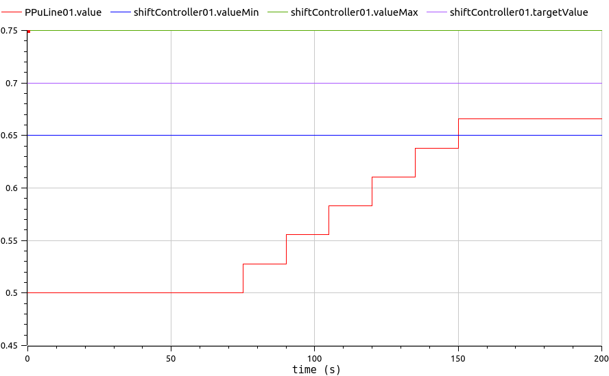
At t = 0s, the phase tap changer transformer is at its centre tap position of 9 and has a phase angle of 0°. It thus does not affect the power flow through the circuit and both lines are equally loaded at 0.5 Pu.
At t = 50s, the phase shifter controller is turned on with a target PMonitored = 0.7 Pu (+/- tolerance) through line01.
The controller then passes several taps down. The resulting negative phase angle (-7.5°) has diverted portion of loading onto the parallel circuit, while the total load supplied is unchanged.

Parameters

TypeNameDefaultDescription
Modelica.SIunits.ImpedanceZBASE69_069.0^2/Dynawo.Electrical.SystemBase.SnRef
Dynawo.Types.VoltageModulePuU0PuGen011.
Dynawo.Types.ActivePowerPuP0PuLoad011.
Dynawo.Types.ReactivePowerPuQ0PuLoad010.
Dynawo.Types.ComplexApparentPowerPus0Pu_load01Complex(P0PuLoad01, Q0PuLoad01)

Connectors

TypeNameDefaultDescription
Dynawo.Connectors.ImPinPPuLine01Active power transitting in line 01 in pu (base SnRef)

Components

TypeNameDefaultDescription
Dynawo.Electrical.Buses.InfiniteBusgen01
Dynawo.Types.ActivePowercheckGen01P
Dynawo.Types.ReactivePowercheckGen01Q
Dynawo.Electrical.Loads.LoadPQload01
Dynawo.Electrical.Controls.Basics.SetPointPrefPuLoad01
Dynawo.Electrical.Controls.Basics.SetPointQrefPuLoad01
Dynawo.Electrical.Buses.Busbus01
Dynawo.Electrical.Buses.Busbus02
Dynawo.Electrical.Buses.Busbus03
Dynawo.Electrical.Transformers.TransformerPhaseTapChangertfo01
Dynawo.Electrical.Lines.Lineline01
Dynawo.Electrical.Lines.Lineline02
Dynawo.Electrical.Controls.Transformers.PhaseShifterPshiftController01