modelDoubleInertialGrid

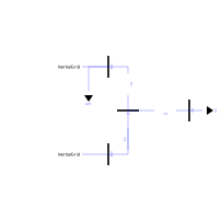
Diagram of DoubleInertialGrid

Extends from Modelica.Icons.Example (Icon for runnable examples).

Information

In this example, two inertial grids are connected together and with a load. It allows to make appearing an interarea oscillation. The frequency of this oscillation can be theoretically calculated using a few approximations (U1 = U2 = 1 for example). It leads to find a mode in the system at the following frequency: f = sqrt(omega0/HX)/2*Pi.
The theoretical derivations are provided in the following paper:

C. Cardozo et al., "Small Signal Stability Analysis of the Angle Difference Control on a HVDC Interconnection Embedded in the CE Synchronous Power System," 2020 IEEE/PES Transmission and Distribution Conference and Exposition (T&D), Chicago, IL, USA, 2020, pp. 1-5, doi: 10.1109/TD39804.2020.9300036.

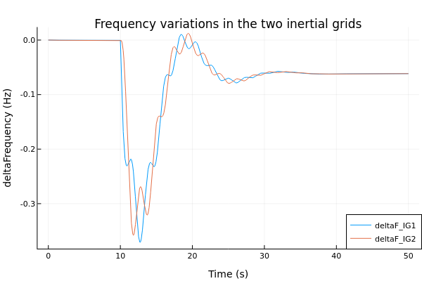
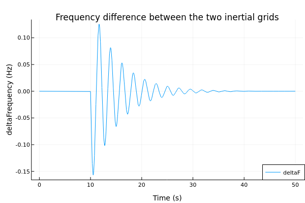
It means that the frequency of the interarea oscillation can be easily moved in a range of frequency. With the particular values provided in this case we obtained a mode at f = 0.45 Hz, as demonstrated by the plots below.

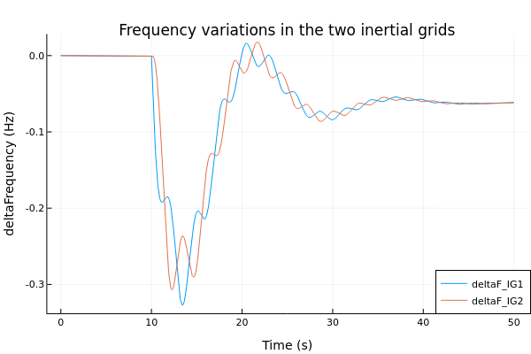
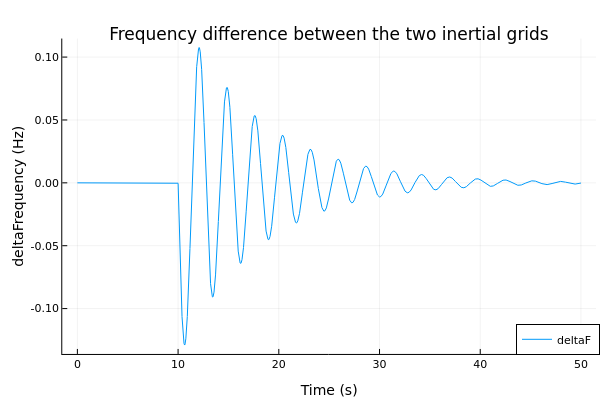
By taking H = 4 for example, we end up with a different mode (f = 0.36 Hz), as visible in the plot below.

The test case can be used and modified to assess the contribution of any device under test to the interarea mode.

Parameters

TypeNameDefaultDescription
Dynawo.Types.VoltageModuleUNom400Nominal voltage for the test case
Dynawo.Types.ActivePowerPudeltaPPu0.05Variation on the PQ load active power in pu (base SNom)
Dynawo.Types.ApparentPowerModuleSNom32350Nominal apparent power of the inertial grids in MVA
Dynawo.Types.PerUnitR1Pu0.02*Dynawo.Electrical.SystemBase.SnRef/(UNom*UNom)Line resistance in pu (base SnRef/UNom) by kilometer for branch 1
Dynawo.Types.PerUnitX1Pu0.27*Dynawo.Electrical.SystemBase.SnRef/(UNom*UNom)Line reactance in pu (base SnRef/UNom) by kilometer for branch 1
Dynawo.Types.PerUnitR2Pu0.02*Dynawo.Electrical.SystemBase.SnRef/(UNom*UNom)Line resistance in pu (base SnRef/UNom) by kilometer for branch 2
Dynawo.Types.PerUnitX2Pu0.27*Dynawo.Electrical.SystemBase.SnRef/(UNom*UNom)Line reactance in pu (base SnRef/UNom) by kilometer for branch 2
Dynawo.Types.PerUnitR3Pu0.18*Dynawo.Electrical.SystemBase.SnRef/(UNom*UNom)Line resistance in pu (base SnRef/UNom) by kilometer for branch 3
Dynawo.Types.PerUnitX3Pu0.81*Dynawo.Electrical.SystemBase.SnRef/(UNom*UNom)Line reactance in pu (base SnRef/UNom) by kilometer for branch 3
RealL1120Branch 1 length (in km)
RealL2120Branch 2 length (in km)
RealL3100Branch 3 length (in km)

Components

TypeNameDefaultDescription
Dynawo.Electrical.Sources.InertialGrid.InertialGridinertialGrid1
Dynawo.Electrical.Sources.InertialGrid.InertialGridinertialGrid2
Dynawo.Electrical.Loads.LoadZIPload
Dynawo.Electrical.Loads.LoadPQloadPQ
Dynawo.Electrical.Buses.BusbusIG1
Dynawo.Electrical.Buses.BusbusIG2
Dynawo.Electrical.Buses.BusbusL
Dynawo.Electrical.Lines.Lineline1
Dynawo.Electrical.Buses.Busbus
Dynawo.Electrical.Lines.Lineline2
Dynawo.Electrical.Lines.Lineline3
Dynawo.Types.FrequencydeltaFrequencyFrequency difference between both inertial grids