modelLeadMOrderLag
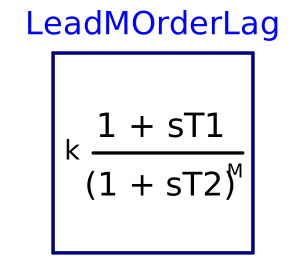
Lead-lag filter with M poles
Extends from Modelica.Blocks.Interfaces.SISO (Single Input Single Output continuous control block).
Information
Model to implement the following transfer function: y 1 + s*t1
- = k * ---------------
u (1 + s*t2)^M
It is required that M > 0. If t1 = 0 and t2 = 0 then the block is a static gain, otherwise it is required that t1 > 0 and t2 > 0.
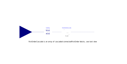
If M > 1, y = firstOrderCascade[M-1].y but for such an equation to be compiled, the value of M has to be known during the compilation, thus making it impossible to change M before the simulation.
A workaround has been found with a vector z of the same size as firstOrderCascade, whose components are either 0 or (for the M-1th) firstOrderCascade[M-1].y. The sum of z is therefore firstOrderCascade[M-1].y.
Parameters
| Type | Name | Default | Description |
|---|---|---|---|
| Real | K | 1 | Gain |
| Integer | M | Lag order | |
| Types.Time | t1 | Lead time constant in s | |
| Types.Time | t2 | Lag time constant in s | |
| Integer | MMax | 6 | Maximum lag order (>= 3) |
| Real | Y0 | 0 | Initial or guess value of output |
Connectors
| Type | Name | Default | Description |
|---|---|---|---|
| RealInput | u (from SISO) | Connector of Real input signal | |
| RealOutput | y (from SISO) | Connector of Real output signal |
Components
| Type | Name | Default | Description |
|---|---|---|---|
| Real[MMax - 1] | z | Intermediate vector whose sum equals firstOrderCascade[M-1].y | |
| Modelica.Blocks.Continuous.FirstOrder[MMax - 1] | firstOrderCascade | ||
| Dynawo.NonElectrical.Blocks.Continuous.TransferFunction | leadlag |