modelTwoPortRLC
Model of an RLC element with two electrical ports
Extends from IDEAS.Electrical.Transmission.BaseClasses.PartialTwoPortRLC.
Information
This model represents a series of two resistive-inductive impedances and a capacitance that connects two AC single phase interfaces. This model can be used to represent a cable in a AC grid.
The model represents the lumped resistances and capacity, as a T-model, as shown in the figure below.
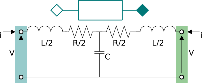
As can be seen in the figure, the resistance R and the inductance L are split in two halves
and the capacitance is located in the center.
The capacitance in the center is optional. If it is not present, set the
parameter C=0.
The model is either dynamic or static depending on the
presence of the capacitive effect.
Parameters
| Type | Name | Default | Description |
|---|---|---|---|
| Modelica.Units.SI.Voltage[2] | Vc_start | {V_nominal, 0} | Initial voltage phasor of the capacitance located in the middle of the line |
| Modeling assumption | |||
| IDEAS.Electrical.Types.Load | mode | IDEAS.Electrical.Types.Load.FixedZ_steady_state | Type of model (e.g., steady state, dynamic, prescribed power consumption, etc.) |
Revisions
-
November 8, 2016, by Michael Wetter:
Addedreplaceableto terminal redeclaration as they are redeclared by IDEAS.Electrical.AC.ThreePhasesBalanced.Lines.TwoPortRLC. -
May 26, 2016, by Michael Wetter:
Moved function call toPhaseSystem.thetaRefout of derivative operator as this is not yet supported by JModelica. -
March 9, 2015, by Marco Bonvini:
Added parameter for start value of the voltage. -
August 5, 2014, by Marco Bonvini:
Revised model and documentation.