modelDetailedHouse1
Extends from Modelica.Icons.Example.
Information
This first example instantiates a simple building model that consists of one zone, four walls, a window, a floor and a ceiling. The zone dimensions are 8 m (with walls oriented north and south) by 4 m, and the window measures 3 m by 1.4 m. Use the default zone height of 2.8 m. Apply double glazing and a heavy wall, which provide high thermal mass.
Required models
- IDEAS.BoundaryConditions.SimInfoManager
- IDEAS.Buildings.Components.Zone
- IDEAS.Buildings.Components.OuterWall
- IDEAS.Buildings.Components.Window
- IDEAS.Buildings.Components.SlabOnGround
Connection instructions
Each yellow bus connector of a surface (Window, OuterWall
or SlabOnGround) has to be connected to exactly one zone bus connector.
To support multiple connections, the zone has an array of bus connectors with size
nSurf, where nSurf is a parameter of Zone,
which has to be set by the user. It is the user’s responsibility to ensure that each
element of this array is connected to exactly one surface and that there is a total
of nSurf connections to the zone.
In addition to connecting each surface, the parameters of each component have to be set. Components typically
have many default values that are appropriate for many purposes. When a parameter does not have a default
value, it must be set by the user. Notable examples are the dimensions and orientation of the zone, walls
and windows. The surface orientation can be set using the parameters incOpt, which automatically sets the
inclination depending on the type of outer wall (wall, floor, ceiling), and aziOpt, which automatically sets the
azimuth (north, east, south, west). Furthermore, the zone Medium must be set to
IDEAS.Media.Air. Glazing and wall types must also be specified. This example uses the BESTEST Heavy Wall for the
walls, the FloorOnGround construction type for the floor, the BESTEST light roof for the roof and the double glazing
type Saint Gobain Planitherm and a south orientation for the window.
The SimInfoManager by default has the modifier inner in its declaration. All IDEAS building components
have the modifier outer in their respective declarations of the SimInfoManager. This causes the component
declarations to point towards the higher level SimInfoManager declaration. This way all model equations for
the weather data have to be generated only once, instead of for each surface.
Reference result
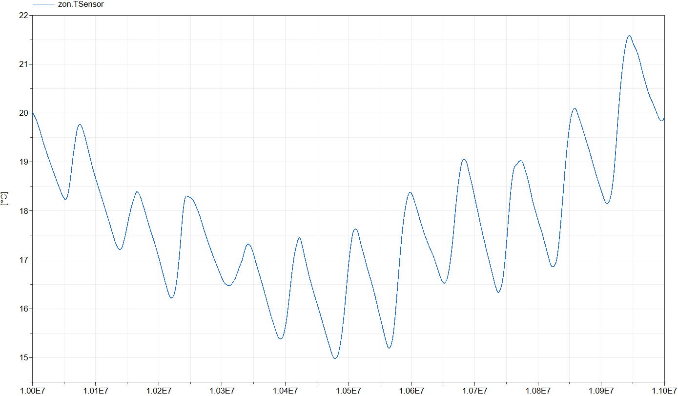
This model is simulated with the following settings:
- Dassl as the solver with tolerance = 1e-06
- Start time = 1e7,
- Stop time = 1.1e7,
- Number of intervals = 5000.
The simulation starts 107 seconds after New Year and ends 106 seconds later, covering a period of 11.6 days.
The figure below shows the operative zone temperature, zon.TSensor,
which represents the mean of the air temperature and the mean radiative temperature of all surfaces.
Parameters
| Type | Name | Default | Description |
|---|---|---|---|
| Modelica.Units.SI.Length | l | 8 | Zone length |
| Modelica.Units.SI.Length | w | 4 | Zone width |
| Modelica.Units.SI.Length | h | zon.hZone | Zone height (Default) |
Components
| Type | Name | Default | Description |
|---|---|---|---|
| IDEAS.BoundaryConditions.SimInfoManager | sim | ||
| IDEAS.Buildings.Components.Zone | zon | Zone model | |
| IDEAS.Buildings.Components.OuterWall | outWalWes | Western outer wall model | |
| IDEAS.Buildings.Components.OuterWall | outWalEas | Eastern outer wall model | |
| IDEAS.Buildings.Components.OuterWall | outWalNor | Northern outer wall model | |
| IDEAS.Buildings.Components.OuterWall | outWalSou | Southern outer wall model | |
| IDEAS.Buildings.Components.Window | win | Window model | |
| IDEAS.Buildings.Components.SlabOnGround | slaOnGro | Floor model | |
| IDEAS.Buildings.Components.OuterWall | cei | Ceiling model |
Contents
| Name | Description |
|---|---|
| MediumAir | Air medium |