packageUsersGuide
Extends from Modelica.Icons.Information.
Information
This package contains a physics-based PVT collector model relying solely on datasheet parameters. The thermal formulation follows the ISO 9806:2017 quasi‑dynamic test standard, which is currently the most widely used test method for both glazed and unglazed (WISC) collectors. The electrical submodel is internally coupled via a datasheet‑derived absorber–fluid heat transfer coefficient.
Model description
Thermal part
The equations related to the heat losses and heat gains can be found in the following models:
- Quasi‑dynamic thermal losses: see IDEAS.Fluid.PVTCollectors.BaseClasses.ISO9806HeatLoss
- Solar (thermal) heat gain: see IDEAS.Fluid.SolarCollectors.BaseClasses.EN12975SolarGain
The thermal parameters used by this model are expressed in the ISO 9806:2017 quasi‑dynamic format.
Because some commercial PVT collectors are still tested under ISO 9806:2013 (steady‑state
unglazed or quasi‑dynamic) or the newly published ISO 9806:2025 quasi‑dynamic method, a
unified conversion procedure is provided to translate datasheet parameters from
these standards into their ISO 9806:2017 equivalents. This guarantees that the
model can be used for all commercially tested PVT collectors. The standard‑to‑standard
conversion routines are provided in the easy‑to‑use Excel file located at
IDEAS.Resources.Data.Fluid.PVTCollectors. The conversion procedure
is based on (i) SKN‑N0474R0 for ISO 9806:2013 to ISO 9806:2017, and (ii) a newly
introduced conversion for ISO 9806:2025 to ISO 9806:2017 as published in Meertens et al. (2026).
Electrical part
The equations and assumptions related to the electrical part can be found in the following model:
- Electrical generation: see IDEAS.Fluid.PVTCollectors.BaseClasses.ElectricalPVT
Electrical–thermal coupling
The internal absorber–fluid heat transfer coefficient UAbsFluid couples the thermal and electrical models by linking the PV cell temperature to the fluid temperature (see Figure 1). This coupling is critical for accurately predicting the electrical output.
The coefficient UAbsFluid is computed solely from datasheet parameters following the method introduced in Meertens et al. (2026). For ISO 9806:2017 and MPP‑tested collectors, the approximate formula is:
| (τ·α)eff – η0,el · (a1 + a3·ur) |
| ((τ·α)eff – η0,el – (1 – a6η0,b · ur) · η0,b |
- Here, (τ·α)eff = 0.901 for unglazed PVT collectors as reported in Lämmle (2018), and 0.84 for covered collectors.
- ur is the in-plane reduced wind speed. In this approximation, ur = 0 is used to derive UAbsFluid. The internal heat transfer coefficient is only weakly dependent on external wind speed when the datasheet thermal parameters are accurate (Stegmann 2011).
This approach removes the need for a hidden fit parameter: both thermal and electrical coupling coefficients derive solely from publicly available datasheet values.
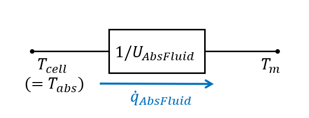
Figure 1: Equivalent thermal network between temperatuur node and cell node interlinked by UAbsFluid (Meertens et al., 2026).
References
- ISO 9806:2017. Solar thermal collectors — Test methods. ISO.
- SKN-N0474R0. Thermal Performance Parameter Conversion to ISO 9806-2017. Solar Heat Europe, 2019.
- Stegmann, M.; Bertram, E.; Rockendorf, G.; Janßen, S. (2011). Model of an Unglazed Photovoltaic Thermal Collector Based on Standard Test Procedures. ISES Solar World Congress proceedings. DOI: 10.18086/swc.2011.19.30
- Lämmle, M. (2018). Thermal management of PVT collectors: development and modelling of highly efficient glazed, flat plate PVT collectors with low emissivity coatings and overheating protection. PhD thesis, University of Freiburg. DOI: 10.6094/UNIFR/16446
- Dobos, A. P. (2014). PVWatts Version 5 Manual. NREL/TP-6A20-62641
- Meertens, L.; Jansen, J.; Helsen, L. (2026). Development and Experimental Validation of an Open-Source Photovoltaic‑Thermal Collector Modelica Model that Only Needs Datasheet Parameters. Submitted to Mathematical and Computer Modelling of Dynamical Systems, Special Issue on Modelica, FMI, and Open Standards.
- Meertens, L., Jansen, J., Helsen, L. (2025). Development and Experimental Validation of an Unglazed Photovoltaic-Thermal Collector Modelica Model that only needs Datasheet Parameters, submitted to the 16th International Modelica & FMI Conference, Lucerne, Switzerland, Sep 8–10, 2025.