modelDefiningGenerationGroups
More Detailed GU Models
Extends from Modelica.Icons.Information (Icon for general information packages).
Information
Adding Generation Unit Models in More Detail
Let us now proceed to create alternative representations of a generation unit so that we can use them in our experiments.
- Expand your
GenerationUnitspackage and duplicate theGeneratorOnlymodel to create a new model calledGeneratorTurbGovthat also has a turbine/governor block.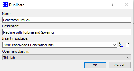
- Go to the diagram layer of the model and drag-and-drop a
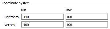
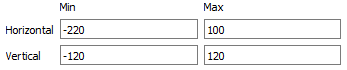
IEEEG1turbine/governor block fromOpenIPSL.Electrical.Controls.PSSE.TG. - It is highly recommended that you increase the dimensions of the canvas so that the components could be better distributed. One way of achieving this is by right-clicking the diagram layer and choosing the Attributes option. In the Graphics tab modify the coordinates as indicated below:
- Remove the connection between the
PMECH0output and thePMECHinput of the machine. Be aware that we now have a turbine block, therefore connect its HP-stage mechanical power output to the corresponding input of the machine. Your model should look like this: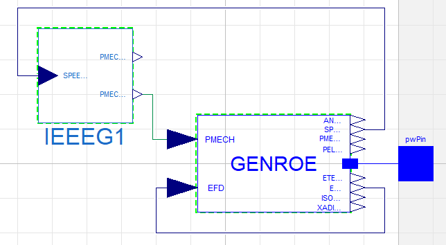
- Provide the following values for the
IEEEG1parameters: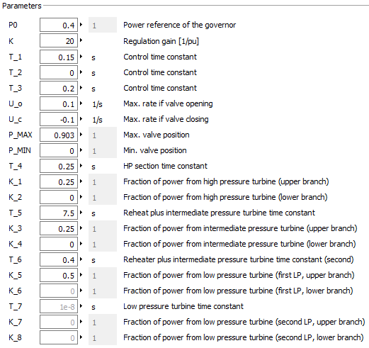
- Check the model and make sure that everything is fine.
- Open the diagram layer of your
SMIBexperiment model and double-click the genunit component. - Go to the Attributes tab and click the replaceable option. Then click the Constraining Clause checkbox and select
OpenIPSL.Interfaces.Generatorfrom the drop-down list.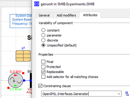
📌 The
GenerationUniticon should now turn into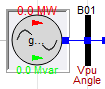
- In Simulation Setup go to the Output tab and make sure that you are keeping at least 10 results:

- Go back to the diagram layer for the
SMIBmodel and right-click the genunit block to change the class to the " Machine with Turbine and Governor" option.
- Simulate the model again for 2 seconds.
- Plot the active power output (P) from genunit and compare it to the result you got from the previous simulation (where the generation unit model did not include the turbine/governor block).
- Create a new generation unit model including the electrical machine, the turbine/governor and an excitation system. Name the new model
GeneratorTurbGovAVR. For this to be done make sure you duplicate theGeneratorTurbGovmodel.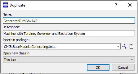
- Drag-and-drop an
ESST1Aexcitation system block fromOpenIPSL.Electrical.Controls.PSSE.ESto the diagram layer of the new model. Add 4Constantblocks fromModelica.Blocks.Sourcestoo. - Increase the dimensions of the diagram layer as required to comfortably resize and connect your components. Check out what we did in step 3. A suggestion is shown below:
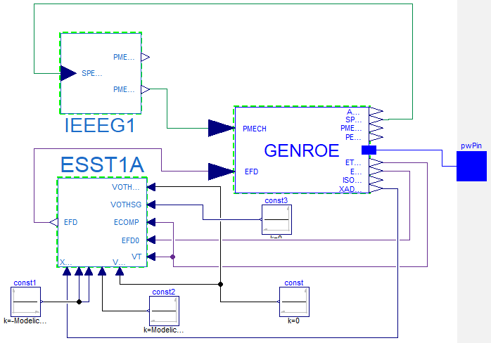
- In the
GENROEmachine component, remove the connection betweenEFDandEFD0. TheEFDinput of the machine should now be connected to the respective output from the excitation system. - Add the following connections between the machine and the excitation system:
GENROE Machine EEST1A ETERM
VT
ETERM
ECOMP
EFD0
EFD0
XADIFD
XADIFD
- Use the
Constantblocks to set the excitation system inputs to the values indicated in the following table:Input Value VOTHSG
0
VOTHSG2
0
VUEL
0
VOEL
Modelica.Constants.inf
VUEL2
-Modelica.Constants.inf
VUEL3
-Modelica.Constants.inf
Your model should now look like this:
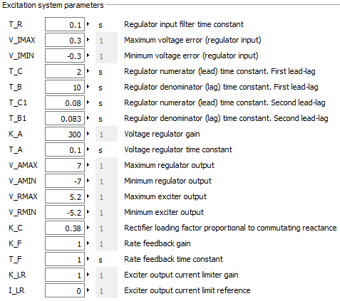
- Double-click the excitation system component and input the parameter values as indicated below:
- Check the generation unit model to verify that everything is fine. Then go to the
SMIBexperiment model and change the class of the genunit component so that it now uses the model with the excitation system. - In the diagram layer of the
SMIBmodel when right-clicking the genunit component, you should now be able to see the new generation unit model among the options for class change. Update the component class so that it uses the most recent generation unit model.
- Simulate the
SMIBmodel for 10 seconds. - Plot the active power (P) and the reactive power (Q) outputs from genunit in different diagrams. Then, plot the voltage (V) from all the buses in another window.
- Go to the
GenerationUnitsGeneratorTurbGovAVR. Name the new modelGeneratorTurbGovAVRPSS. This generation unit model is going to include a power system stabilizer (PSS).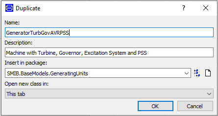
- Navigate the
OpenIPSL.Electrical.Controls.PSSE.PSSpackage and locate thePSS2Amodel (Dual-Input Stabilizer Model [IEEE1992]). Drag-and-drop an instance to the diagram layer of the new generation unit model. - Remove the constant source block that is connected to the
VOTHSGinput of the excitation system component. Now this input should be connected to the output of thePSS2Ablock. - Connect the
V_S1andV_S2inputs of thePSS2Ablock to theSPEED_HPandPELECoutputs of the machine component, respectively.Make sure that your model looks like the figure below:
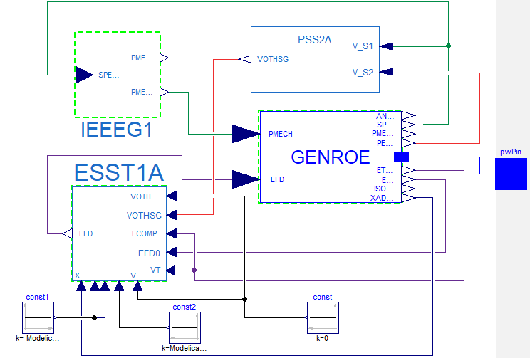
- Double-click the
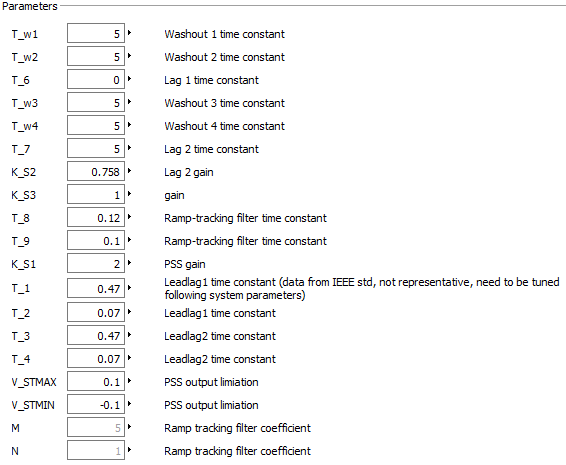
PSS2Acomponent in order to update the parameters as indicated below: