
modelSMIBSystemAssembly
Assembling a SMIB System
Extends from Modelica.Icons.Information (Icon for general information packages).
Information
Assembling a SMIB System
- Open Dymola.
- Load the OpenIPSL library.
- Create a new package called
SMIB. Make sure to unselect the option to save the contents of the package in one file.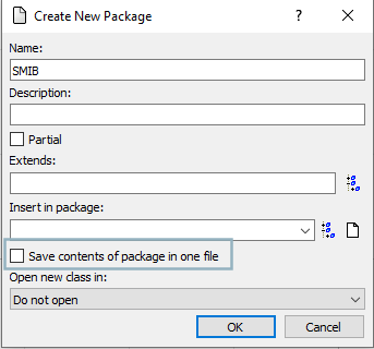
- Inside
SMIBcreate two sub-packages namedExperimentsandBaseModels. Then add two sub-packages insideBaseModelscalledGenerationUnitsandBaseNetwork. Once again, remember to keep the option to " save the contents of the package in one file" unselected. - To follow the structure and appearance convention of packages in Modelica, we can add an icon to the
Experimentspackage. Double-click theExperimentspackage and go to the text layer to add the following line of class extension:package Experiments extends Modelica.Icons.Example; end Experiments; - Inside
BaseNetwork, create a new partial model calledSMIBPartial. - Go to the Package Browser, navigate to
OpenIPSL.Interfaces.Generator, and right-click the icon to create a new model by class extension. Name the new modelInfiniteBusand place it insideGenerationUnits.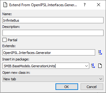
- Repeat the procedure to create a new model called
GeneratorOnly. Your package should look as follows: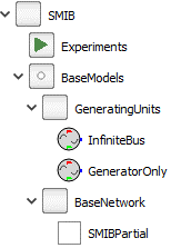
- Inside
InfiniteBus, drag and drop aGENCLSgenerator model fromOpenIPSL.Electrical.Machines.PSSE. - Connect the blue pin of the
GENCLScomponent topwPin. - Now drag and drop a
GENROEgenerator model fromOpenIPSL.Electrical.Machines.PSSEtoGeneratorOnly.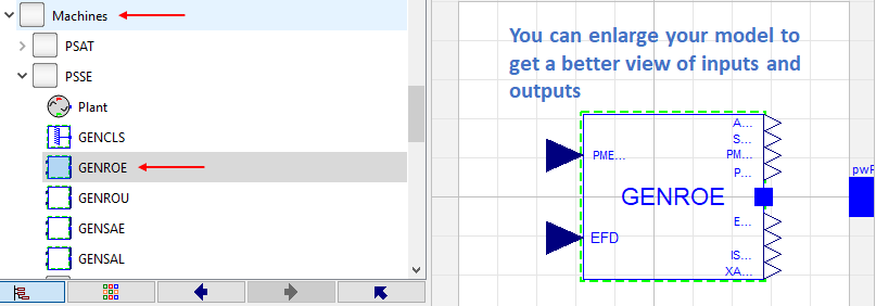
- Connect the output pin
PMECH0on the right to the input pinPMECHon the left of theGENROEblock. Do the same for theEFD0output and inputEFDon the bottom. Also, connect the blue pin topwPin. Your connections should look as follows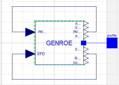
- Double click the
GENCLSblock inside theInfiniteBusmodel. Be sure to enter all the machine parameters in the figure below: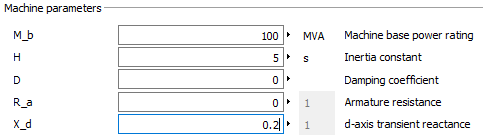
- Switch to the Modelica Text of the
InfiniteBusmodel. Propagate the power flow parameters one layer up as indicated in the highlighted text of the following code chunk:model InfiniteBus extends OpenIPSL.Interfaces.Generator; OpenIPSL.Electrical.Machines.PSSE.GENCLS gENCLS(P_0=P_0, Q_0=Q_0, v_0=v_0, angle_0=angle_0, M_b=100000000, H=5.0000, D=0.0000, R_a=0.0000, X_d=0.2000) a..; equation connect(gENCLS.p, pwPin) a..; end InfiniteBus; - Go to the diagram layer of the
GeneratorOnlymodel, double click theGENROEcomponent and fill in the power flow data fields. Notice that no explicit values should be passed tov_0(V_0in OpenIPSL 1.5),angle_0,P_0, andQ_0. These values are propagated from an upper layer.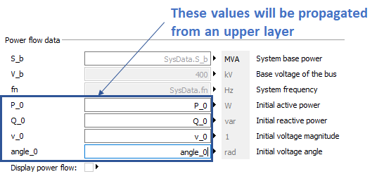
- Similarly, pass the dynamical machine parameters to the generator model
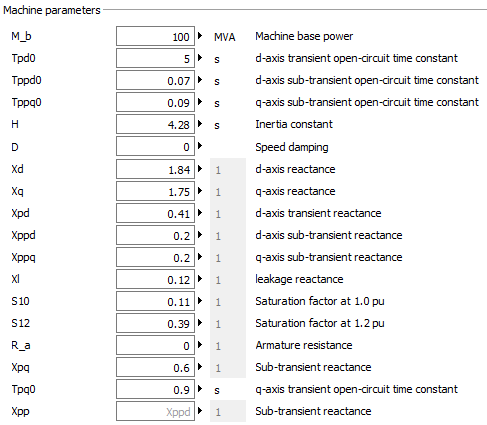
- Go now to the diagram layer of the
SMIBPartialmodel. Drag and drop the following components:- four buses from
OpenIPSL.Buses.Bus(you could also work withOpenIPSL.Buses.BusExt); - four lines from
OpenIPSL.Branches.PwLine; - a
LoadfromOpenIPSL.Electrical.Loads.PSSE; - a
PwFaultfromOpenIPSL.Electrical.Events; - a
SystemBasefromOpenIPSL.Electrical.SystemBase. Set the base frequency to 50 Hz and the base to 100 MVA; - an
InfiniteBusgeneration unit.
- four buses from
- Connect and name the different components as shown below:
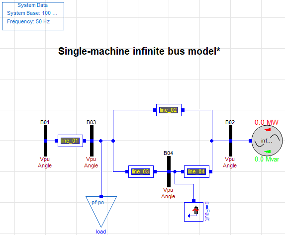
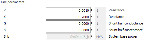
- Enter the parameters for each of the four lines, as indicated in the corresponding table at the beginning of this document. For example, lines 1 and 2 should have the following parameters:
- Click the
B01component and select the option to display the power flow. Do the same for the remaining buses and the generation unit component. - Double click the
pwFaultblock and fill in the parameters as indicated below:
- Inside
Experimentscreate a new model named SMIB by extending theSMIBPartialmodel. Although not entirely required, add the following line to the Modelica text to include an icon to the model:model SMIB extends Modelica.Icons.Example; extends BaseModels.BaseNetwork.SMIBPartial; end SMIB;
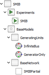
📌 You should have a package structure similar to this:
- Drag-and-drop a
GeneratorOnlycomponent from theGenerationUnitspackage to the diagram layer of the SMIB model. Name it genunit and make sure that the Display power flow option inside its parameters window is checked. - Connect
genunitto busB01. The model should look as follows: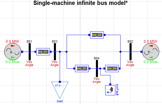
- Save your models. You should see several .mo files accompanying the model inside a folder called
SMIB. - Close Dymola or unload your SMIB model.