
modelTestLeadLagWithNonWindupLimiter
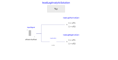
Extends from Modelica.Icons.Example (Icon for runnable examples).
Information
This model demonstrates the correct behaviour of the LeadLagWithNonWindupLimiter by computing the response to a suitable signal and comparing it to the known analytic solution. The blocks are initialized in steady state.
The first filter has k = 2, T1 = 1, T2 = 2, yMax = 5, yMin = -5, while the second has an opposite gain k = -2 and is fed with the opposite input signal, so the output is the same, since the output limits are symmetrical.
Components
| Type | Name | Default | Description |
|---|---|---|---|
| PowerGrids.Controls.LeadLagWithNonWindupLimiter | leadLagPositiveGain | ||
| Modelica.Blocks.Sources.TimeTable | inputSignal | ||
| Modelica.Blocks.Sources.RealExpression | leadLagAnalyticSolution | ||
| PowerGrids.Controls.LeadLagWithNonWindupLimiter | leadLagNegativeGain | ||
| Modelica.Blocks.Math.Gain | negativeGain |