
modelCompressor
Gas compressor
Information
## Copyright © EDF 2002 - 2026
## ThermoSysPro Version 4.2
This component model is documented in Sect. 11.3 of the ThermoSysPro book.
# Static compressor
Most modern combustion turbines use multistage axial compressors. The pressure of the atmospheric air flowing through is increased up to 30 times.
The mass flow rate of inlet air increases when the ambient temperature decreases.
## Modelica component model
The equations mentioned below are implemented in the component *Compressor*, located in the *FlueGases.Machines* sub-library.
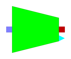
The component has 3 connectors:
- Ce: flue gases at the inlet,
- Cs: flue gases at the outlet,
- Power: compressor power output.

## Nomenclature
| Symbol| Description| Unit| Definition| Modelica name|
| :-------------------- | :------------------------------------------------------- | :------------------------------- | :---------------------------------- |:---------------------------------- |
| \\(h\_{\mathrm{i}}\\)| Fluid specific enthalpy at the inlet| \\(\mathrm{J} / \mathrm{kg}\\)||He|
| \\(h\_{\mathrm{is}}\\)| Fluid specific enthalpy after the isentropic compression | \\(\mathrm{J} / \mathrm{kg}\\)||His|
| \\(h\_{\mathrm{o}}\\)| Fluid specific enthalpy at the outlet| \\(\mathrm{J} / \mathrm{kg}\\)||Hs|
| \\(m\\)| Fluid mass flow rate| \\(\mathrm{kg} / \mathrm{s}\\)| \\(q \cdot \rho\_{\mathrm{i}}\\)|Q|
| \\(P\_{\mathrm{i}}\\)| Fluid pressure at the inlet| \\(\mathrm{Pa}\\)||Pe|
| \\(P\_{\mathrm{o}}\\)| Fluid pressure at the outlet| \\(\mathrm{Pa}\\)||Ps|
| \\(q\\)| Fluid volumetric flow rate| \\(\mathrm{m}^{3} / \mathrm{s}\\)||Qv|
| \\(W\_{\mathrm{c}}\\)| Compressor power \(negative value\)| \\(\mathrm{W}\\)||Wcp|
| \\(X\\)| Ratio between the actual and nominal compression rate| \\(-\\)| \\(\pi / \pi\_{n}\\)|Xtau|
| \\(\eta\\)| Isentropic efficiency| \\(-\\)||is_eff|
| \\(\eta\_{\mathrm{n}}\\) | Nominal isentropic efficiency| \\(-\\)||is_eff_n|
| \\(\pi\\)| Compression rate| \\(-\\)| \\(P\_{\mathrm{o}} / P\_{\mathrm{i}}\\)|tau|
| \\(\pi\_{\mathrm{n}}\\)| Nominal compression rate| \\(-\\)||tau_n|
| \\(\rho\_{\mathrm{i}}\\) | Fluid density at the inlet| \\(\mathrm{kg} / \mathrm{m}^{3}\\) ||rho_e|
## Governing equations
The steady-state model is based on a polynomial equation of the isentropic efficiency obtained by experimental data from several combined cycle power plants.
### Fluid specific enthalpy at the outlet of the compressor
- Validity domain:
\\(\forall h\_{\mathrm{i}}\\)
- Mathematical formulation:
$$h\_{\mathrm{o}}=h\_{\mathrm{i}}+\frac{\left\(h\_{\mathrm{is}}-h\_{\mathrm{i}}\right\)}{\eta\_{\mathrm{is}}}$$
- Comments:
### Compressor power
- Validity domain:
\\(\dot{m} \geq 0\\)
- Mathematical formulation:
$$W\_{\mathrm{c}}=\dot{m} \cdot\left\(h\_{\mathrm{i}}-h\_{0}\right\)$$
- Comments:
### Isentropic efficiency
- Validity domain:
\\(X>0\\)
- Mathematical formulation:
$$\eta=f\_{\eta}\(X\) \cdot \eta\_{n}$$
- Comments:
\\( f\_{\eta}\(X\)\\) is the compressor map expressed as a polynomial function of \\(X\\).
## References
El Hefni, Baligh and Bouskela, Daniel (2019). [Modeling and Simulation of Thermal Power Plants with ThermoSysPro](https://link.springer.com/book/10.1007/978-3-030-05105-1), sect. 11.3. Springer Nature Switzerland AG.
Parameters
| Type | Name | Default | Description |
|---|
| Integer | mass_flow_rate_comp | 1 | Ways for computing the mass flow rate - 1: Q = rho*Qv - 2: Q = rho*f(T) |
| Units.SI.Temperature | Tmax | 284.16 | Air transition temperature between f1 = a*x + b and f2 = c*x + d for the computation of Q (active if mass_flow_rate_comp == 2) |
| Real | coef1_1 | 0.1164 | Coefficient a for f1 = a*x + b |
| Real | coef2_1 | 38.643 | Coefficient b for f1 = a*x + b |
| Real | coef1_2 | -0.2324 | Coefficient c for f2 = c*x + d |
| Real | coef2_2 | 137.49 | Coefficient d for f2 = c*x + d |
| Real | A4 | -1.2362 | Coefficient of X^4 for the computation of the isentropic efficiency |
| Real | A3 | 3.6721 | Coefficient of X^3 for the computation of the isentropic efficiency |
| Real | A2 | -4.2434 | Coefficient of X^2 for the computation of the isentropic efficiency |
| Real | A1 | 2.3957 | Coefficient of X^1 for the computation of the isentropic efficiency |
| Real | A0 | 0.4118 | Coefficient of X^0 for the computation of the isentropic efficiency |
| Real | tau_n | 14.149 | Nominal compression rate |
| Real | is_eff_n | 0.84752 | Nominal isentropic efficiency |
Revisions
Author

Baligh El Hefni