Information
## Copyright © EDF 2002 - 2026
## ThermoSysPro Version 4.2
This component model is documented in Chapter 15 of the ThermoSysPro book.
# Alternating engine
The alternating engine is a heat engine that converts thermal and kinetic energy of the combustions into mechanical energy.
Similarly to a gas turbine, the combustion and conversion processes take place at the same time in the combustion chamber.
In the combustion chamber, energy is added by spraying fuel into the air.
The fuel ignition generates high-temperature high-pressure flue gases.
The force from the expanding gas is transferred to the piston in order to rotate the crankshaft. The engine is cooled with water.
The heat engine presented here works according to the four-stroke-cycle principle based on the Beau de Rochas cycle or the Otto cycle.
The cycle is considered as a polytropic process with both heat and work transfer to the surroundings.
The species in the flue gases at the exhaust are governed by the following
chemical reactions:
$$ C + O_2 \longrightarrow CO_2 \\ 4 H + O_2 \longrightarrow 2H_{2}O \\ S + O_2 \longrightarrow SO_2$$
The flue gases also contain excess air in the form of oxygen and nitrogen.
Following assumptions are made:
- the combustion is complete, i.e there is no unburnt fuel
- the air and flue gases follow a polytropic compression.
## Modelica component model
The equations mentioned below are implemented in the component *AlternatingEngine*, located in the *MultiFluids.Machines* sub-library.
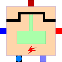
The component has 5 connectors:
- Cws1: water/steam flow at the inlet,
- Cws2: water/steam flow at the outlet,
- Cair: air at the inlet,
- Cfuel: fuel at the inlet,
- Cfg: flue gases at the outlet.

## Nomenclature
| Symbol| Description| Unit| Definition|
| :-------------------------------------------- | :--------------------------------------------------------------------------------------------------------------------------------------- | :---------------------------------------- | :------------------------------------------------------------------------------------------------------------------------------------- |
| \\(c\_{\mathrm{p}, \mathrm{a}}\\)| Air specific heat capacity| \\(\mathrm{J} / \mathrm{kg} / \mathrm{K}\\) ||
| \\(c\_{\mathrm{p}, \mathrm{f}}\\)| Fuel specific heat capacity| \\(\mathrm{J} / \mathrm{kg} / \mathrm{K}\\) ||
| \\(c\_{\mathrm{p}, \mathrm{g}}\\)| Flue gases specific heat capacity at the end of the combustion phase| \\(\mathrm{J} / \mathrm{kg} / \mathrm{K}\\) ||
| \\(c\_{\mathrm{p}, \mathrm{g}}^{23}\\)| Flue gases specific heat capacity between point 2 and point 3| \\(\mathrm{J} / \mathrm{kg} / \mathrm{K}\\) ||
| \\(E\_{\mathrm{X}}\\)| Dry air stoichiometry necessary for the combustion of one kilogram of fuel \(theoretical dry air requirement\)| \\(-\\)||
| \\(E\_{\mathrm{X}, \mathrm{a}}\\)| Combustion air ratio \(excess air factor\)| \\(-\\)| \\(\frac{\dot{m}\_{\mathrm{a}} \cdot\left\(1-X\_{\mathrm{h} 2 \mathrm{o}, \mathrm{a}}\right\)}{\dot{m}\_{\mathrm{f}} \cdot E\_{\mathrm{X}}}\\) |
| \\(h\_{\mathrm{a}, \mathrm{i}}\\)| Air specific enthalpy at the intake| \\(\mathrm{J} / \mathrm{kg}\\)||
| \\(\tilde{h}\_{\mathrm{a}, \mathrm{r}}\\)| Air reference specific enthalpy| \\(\mathrm{J} / \mathrm{kg}\\)| \\(2501569 \cdot X\_{\mathrm{h} 20, \mathrm{a}}\\)|
| \\(h\_{\mathrm{f}}\\)| Fuel specific enthalpy at the intake| \\(\mathrm{J} / \mathrm{kg}\\)| \\(c\_{\mathrm{p}, \mathrm{f}} \cdot\left\(T\_{\mathrm{f}}-273.16\right\)\\)|
| \\(\tilde{h}\_{\mathrm{f}, \mathrm{r}}\\)| Fuel reference specific enthalpy| \\(\mathrm{J} / \mathrm{kg}\\)| 0|
| \\(h\_{\mathrm{g}, \mathrm{o}}\\)| Flue gases specific enthalpy at the exhaust| \\(\mathrm{J} / \mathrm{kg}\\)||
| \\(\tilde{h}\_{\mathrm{g}, \mathrm{r}}\\)| Flue gases reference specific enthalpy| \\(\mathrm{J} / \mathrm{kg}\\)| \\(2501569 \cdot X\_{\mathrm{h} 20, \mathrm{g}}\\)|
| \\(h\_{\mathrm{w}, \mathrm{i}}\\)| Water specific enthalpy at the inlet| \\(\mathrm{J} / \mathrm{kg}\\)||
| \\(h\_{\mathrm{w}, \mathrm{o}}\\)| Water specific enthalpy at the outlet| \\(\mathrm{J} / \mathrm{kg}\\)||
| \\(\mathrm{LHV}\\)| Fuel lower heating value| \\(\mathrm{J} / \mathrm{kg}\\)||
| \\(\dot{m}\_{\mathrm{a}}\\)| Air mass flow rate| \\(\mathrm{kg} / \mathrm{s}\\)||
| \\(m\_{\mathrm{g}}\\)| Flue gases mass flow rate| \\(\mathrm{kg} / \mathrm{s}\\)||
| \\(m\_{\mathrm{f}}\\)| Fuel mass flow rate \(crude fuel\)| \\(\mathrm{kg} / \mathrm{s}\\)||
| \\(m\_{\mathrm{w}}\\)| Cooling water mass flow rate| \\(\mathrm{kg} / \mathrm{s}\\)||
| \\(M\_{\mathrm{a}}\\)| Air molar mass| \\(\mathrm{kg} / \mathrm{kmol}\\)| 28.9|
| \\(M\_{\mathrm{af}}\\)| Air-fuel mixture molar mass| \\(\mathrm{kg} / \mathrm{kmol}\\)||
| \\(M\_{\mathrm{co}\_{2}}\\)| \\(\mathrm{CO}\_{2}\\) molar mass| \\(\mathrm{kg} / \mathrm{kmol}\\)| \\(M\_{\mathrm{C}}+2 \cdot M\_{\mathrm{O}}\\)|
| \\(M\_{\mathrm{h}\_{2} \mathrm{o}}\\)| \\(\mathrm{H}\_{2} \mathrm{O}\\) molar mass| \\(\mathrm{kg} / \mathrm{kmol}\\)| \\(M\_{\mathrm{O}}+2 \cdot M\_{\mathrm{H}}\\)|
| \\(M\_{\mathrm{so}\_{2}}\\)| \\(\mathrm{SO}\_{2}\\) molar mass| \\(\mathrm{kg} / \mathrm{kmol}\\)| \\(M\_{\mathrm{S}}+2 \cdot M\_{\mathrm{O}}\\)|
| \\(M\_{\mathrm{C}}\\)| Carbon atomic mass| \\(\mathrm{kg} / \mathrm{kmol}\\)| 12.01115|
| \\(M\_{\text {fuel }}\\)| Fuel molar mass| \\(\mathrm{kg} / \mathrm{kmol}\\)||
| \\(M\_{\mathrm{g}}\\)| Flue gases molar mass| \\(\mathrm{kg} / \mathrm{kmol}\\)||
| \\(M\_{\mathrm{H}}\\)| Hydrogen atomic mass| \\(\mathrm{kg} / \mathrm{kmol}\\)| 1.00797|
| \\(M\_{\mathrm{O}}\\)| Oxygen atomic mass| \\(\mathrm{kg} / \mathrm{kmol}\\)| 15.9994|
| \\(M\_{\mathrm{N}}\\)| Nitrogen atomic mass| \\(\mathrm{kg} / \mathrm{kmol}\\)| 14|
| \\(M\_{\mathrm{S}}\\)| Sulfur atomic mass| \\(\mathrm{kg} / \mathrm{kmol}\\)| 32.064|
| \\(n\_{\mathrm{c}}\\)| Compression polytropic index| \\(-\\)||
| \\(n\_{\mathrm{e}}\\)| Expansion polytropic index| \\(-\\)||
| \\(P\_{\mathrm{a}, \mathrm{i}}\\)| Air pressure at the intake| \\(\mathrm{Pa}\\)||
| \\(P\_{\mathrm{a}, 2}\\)| Air-fuel mixture pressure at the end of the compression phase| \\(\mathrm{Pa}\\)||
| \\(P\_{\mathrm{g}, \mathrm{o}}\\)| Flue gases pressure at the exhaust| \\(\mathrm{Pa}\\)| \\(P\_{\mathrm{a}, \mathrm{i}}-\Delta P\_{\mathrm{f}}\\)|
| \\(P\_{\mathrm{g}, 3}\\)| Flue gases pressure at the end of the combustion phase| \\(\mathrm{Pa}\\)||
| \\(P\_{\mathrm{g}, 4}\\)| Flue gases pressure at the end of the expansion phase| \\(\mathrm{Pa}\\)||
| \\(P\_{\mathrm{w}, \mathrm{i}}\\)| Water pressure at the inlet| \\(\mathrm{Pa}\\)||
| \\(P\_{\mathrm{w}, \mathrm{o}}\\)| Water pressure at the outlet| \\(\mathrm{Pa}\\)||
| \\(R\_{\mathrm{v}}\\)| Engine volume ratio: volume of the piston at the end the expansion phase divided by the volume of the piston after the compression phase | \\(-\\)||
|| Air temperature at the intake| \\(\mathrm{K}\\)||
| \\(T\_{\mathrm{a}, \mathrm{i}}\\)| Fuel temperature at the intake| \\(\mathrm{K}\\)||
| \\(T\_{\mathrm{f}}\\)| \\(\mathrm{Flue}\\) gases temperature at the exhaust| \\(\mathrm{K}\\)||
| \\(T\_{\mathrm{g}, \mathrm{o}}\\)||||
| \\(T\_{\mathrm{g}, 3}\\)| Flue gases temperature at the end of the combustion phase| \\(\mathrm{K}\\)||
| \\(T\_{\mathrm{g}, 4}\\)| Flue gases temperature at the end of the expansion phase| \\(\mathrm{K}\\)||
| \\(T\_{\mathrm{m}, 1}\\)| Air-fuel mixture temperature| \\(\mathrm{K}\\)||
| \\(T\_{\mathrm{m}, 2}\\)| Air-fuel mixture temperature at the end of the compression phase| \\(\mathrm{K}\\)||
| \\(W\_{\mathrm{m}}\\)| Engine mechanical power| \\(\mathrm{W}\\)||
| \\(X\_{\mathrm{co}, \mathrm{a}}\\)| \\(\mathrm{CO}\_{2}\\) mass fraction in the air at the intake| \\(-\\)||
| \\(X\_{\mathrm{c} 0, \mathrm{g}}\\)| \\(\mathrm{CO}\_{2}\\) mass fraction in the flue gases| \\(-\\)||
| \\(X\_{\mathrm{h}\_{2} \mathrm{o}, \mathrm{a}}\\) | \\(\mathrm{H}\_{2} \mathrm{O}\\) mass fraction in the air at the intake| \\(-\\)||
| \\(X\_{\mathrm{h}\_{2} \mathrm{o}, \mathrm{g}}\\) | \\(\mathrm{H}\_{2} \mathrm{O}\\) mass fraction in the flue gases| \\(-\\)||
| \\(X\_{\mathrm{o}\_{2}, \mathrm{a}}\\)| \\(\mathrm{O}\_{2}\\) mass fraction in the air at the intake| \\(-\\)||
| \\(X\_{\mathrm{o}\_{2}, g}\\)| \\(\mathrm{O}\_{2}\\) mass fraction in the flue gases| \\(-\\)||
| \\(X\_{\mathrm{so}\_{2}, \mathrm{a}}\\)| \\(\mathrm{SO}\_{2}\\) mass fraction in the air at the intake| \\(-\\)||
| \\(X\_{\mathrm{so}\_{2}, \mathrm{g}}\\)| \\(\mathrm{SO}\_{2}\\) mass fraction in the flue gases| \\(-\\)||
| \\(X\_{\mathrm{C}, \mathrm{f}}\\)| \\(\mathrm{C}\\) mass fraction in the fuel| \\(-\\)||
| \\(X\_{\mathrm{CD}, \mathrm{f}}\\)| Ashes mass fraction in the fuel| \\(-\\)||
| \\(X\_{\mathrm{H}, \mathrm{f}}\\)| \\(\mathrm{H}\\) mass fraction in the fuel| \\(-\\)||
| \\(X\_{\mathrm{O}, \mathrm{f}}\\)| \\(\mathrm{O}\\) mass fraction in the fuel| \\(-\\)||
| \\(X\_{\mathrm{S}, \mathrm{f}}\\)| S mass fraction in the fuel| \\(-\\)||
| \\(X\_{\text {lth }}\\)| Thermal loss fraction to the ambient| \\(-\\)||
| \\(X\_{\mathrm{lw}}\\)| Thermal loss fraction to the cooling water| \\(-\\)| \\(100 \cdot \frac{\Delta P\_{\mathrm{w}}}{P\_{\mathrm{w}, \mathrm{i}}}\\)|
| \\(\delta P\_{\mathrm{w}}\\)| Water pressure loss as percent of the pressure at the inlet| \\(-\\)| \\(\mathrm{Pa}\\)|
| \\(\Delta P\_{\mathrm{f}}\\)| Pressure difference between the air pressure at the intake and the flue gases pressure at the exhaust|||
| \\(\Delta P\_{\mathrm{w}}\\)| Water pressure loss| \\(\mathrm{Pa}\\)| \\(P\_{\mathrm{w}, \mathrm{i}}-P\_{\mathrm{w}, \mathrm{o}}\\)|
| \\(\gamma\\)| Flue gases heat capacity ratio| \\(-\\)| \\(\frac{c\_{p}}{c\_{v}}\\)|
| \\(\eta\_{\mathrm{m}}\\)| Engine mechanical efficiency| \\(-\\)||
| \\(\Lambda\\)| Pressure loss coefficient in the combustion chamber| \\(\mathrm{m}^{-4}\\)||
## Governing equations
### Mass balance equation for the flue gases
- Validity domain:
\\(\dot{m}\_{\mathrm{a}} \geq 0\\) and \\(\dot{m}\_{\mathrm{f}} \geq 0\\)
- Mathematical formulation:
$$\dot{m}\_{\mathrm{g}}=\dot{m}\_{\mathrm{a}}+\dot{m}\_{\mathrm{f}}$$
- Comments:
Flue gases result from the combustion of fuel with air. It is assumed that there is no unburnt fuel.
### Engine mechanical power
- Validity domain:
\\(\dot{m}\_{\mathrm{f}} \geq 0\\)
- Mathematical formulation:
$$W\_{\mathrm{m}}=\eta\_{\mathrm{m}} \cdot \dot{m}\_{\mathrm{f}} \cdot \mathrm{LHV}$$
- Comments:
The fuel lower heating value LHV is the total heat produced by the combustion, minus the amount of heat necessary to vaporize the water contained in the fuel and the water produced during the hydrogen combustion process. Only the LHV is converted into mechanical energy. The efficiency of the energy conversion is given by \\(\eta\_{\mathrm{m}} .\\)
### Energy balance equation for the cooling water
- Validity domain:
\\(\dot{m}\_{\mathrm{w}} \neq 0\\)
- Mathematical formulation:
$$X\_{l \mathrm{w}} \cdot \dot{m}\_{\mathrm{f}} \cdot \mathrm{L} \mathrm{HV}=\dot{m}\_{\mathrm{w}} \cdot\left\(h\_{\mathrm{w}, \mathrm{i}}-h\_{\mathrm{w}, \mathrm{o}}\right\)$$
- Comments:
This equation computes the specific enthalpy \\(h\_{\mathrm{w}, \mathrm{o}}\\) of the cooling water at the outlet from the fraction of combustion heat \\(X\_{\mathrm{lw}}\\) released to the water.
### Flue gases specific enthalpy at the exhaust
- Validity domain:
\\(\dot{m}\_{\mathrm{f}} \geq 0\\)
- Mathematical formulation:
$$\dot{m}\_{\mathrm{f}} \cdot\left\(h\_{\mathrm{f}}+\mathrm{LHV}\right\)+\dot{m}\_{\mathrm{a}} \cdot h\_{\mathrm{a}, \mathrm{i}}=W\_{\mathrm{m}}+\dot{m}\_{\mathrm{g}} \cdot h\_{\mathrm{g}, \mathrm{o}}+\left\(X\_{\mathrm{lth}}+X\_{\mathrm{lw}}\right\) \cdot \dot{m}\_{\mathrm{f}} \cdot \mathrm{LHV}$$
- Comments:
This equation calculates the specific enthalpy \\(h\_{\mathrm{g}, \mathrm{o}}\\) of the flue gases at the exhaust using the conservation of energy over the whole cycle.
### Air-fuel mixture temperature at the intake
- Validity domain:
\\(\dot{m}\_{\mathrm{a}} \neq 0\\) or \\(\dot{m}\_{\mathrm{f}} \neq 0\\)
- Mathematical formulation:
$$T\_{\mathrm{m}, 1} \cdot\left\(\dot{m}\_{\mathrm{f}} \cdot c\_{\mathrm{p}, \mathrm{f}}+\dot{m}\_{\mathrm{a}} \cdot c\_{\mathrm{p}, \mathrm{a}}\right\)=\dot{m}\_{\mathrm{f}} \cdot c\_{\mathrm{p}, \mathrm{f}} \cdot T\_{\mathrm{f}}+\dot{m}\_{\mathrm{a}} \cdot c\_{\mathrm{p}, \mathrm{a}} \cdot T\_{\mathrm{a}}$$
- Comments:
This equation calculates the mixing temperature \\(T\_{\mathrm{m}, 1}\\) of the fuel and the air at the beginning of the cycle. Before the mixing, the fuel and the air are at different temperatures, respectively denoted by \\(T\_{f}\\) and \\(T\_{a}\\). After the mixing, they are at the same temperature \\(T\_{\mathrm{m}, 1}\\). Mixing occurs at constant pressure without any heat exchange to the outside the enthalpy remains constant.
### Air-fuel mixture pressure at the end of the compression phase
- Validity domain:
\\(\forall P\_{\mathrm{a}, \mathrm{i}}\\) and \\(\forall P\_{\mathrm{a}, 2}\\)
- Mathematical formulation:
$$\frac{P\_{\mathrm{a}, 2}}{P\_{\mathrm{a}, \mathrm{i}}}=R\_{\mathrm{v}}^{n\_{\mathrm{c}}}$$
- Comments:
This equation calculates the pressure \\(P\_{\mathrm{a}, 2}\\) at the end of the compression, assuming that the air follows a polytropic compression.
### Air-fuel mixture temperature at the end of the compression phase
- Validity domain:
\\(\forall T\_{\mathrm{m}, 1}\\) and \\(\forall T\_{\mathrm{m}, 2}\\)
- Mathematical formulation:
$$\frac{T\_{\mathrm{m}, 2}}{T\_{\mathrm{m}, 1}}=R\_{\mathrm{v}}^{n\_{\mathrm{c}}-1}$$
- Comments:
This equation calculates the temperature \\(T\_{\mathrm{m}, 2}\\) at the end of the compression phase under the assumption that flue gases follow the ideal gas law.
### Flue gases pressure at the end of the combustion phase
- Validity domain:
\\(\forall P\_{\mathrm{a}, 2}, \forall T\_{\mathrm{m}, 2}, \forall P\_{\mathrm{g}, 3}\\) and \\(\forall T\_{\mathrm{g}, 3}\\)
- Mathematical formulation:
$$\frac{P\_{\mathrm{g}, 3}}{P\_{\mathrm{a}, 2}}=\frac{T\_{\mathrm{g}, 3}}{T\_{\mathrm{m}, 2}} \cdot \frac{M\_{\mathrm{af}}}{M\_{\mathrm{g}}}$$
- Comments:
This equation calculates the pressure at the end of the combustion phase \\(P\_{\mathrm{g}, 3},\\) using the ideal gas law. It is assumed that air contains nitrogen \\(\left\(\mathrm{N}\_{2}\right\)\\) and oxygen \\(\left\(\mathrm{O}\_{2}\right\)\\) only.
### Flue gases temperature at the end of the combustion phase
- Validity domain:
\\(\dot{m}\_{\mathrm{f}} \geq 0\\) and \\(\dot{m}\_{\mathrm{g}}>0\\)
- Mathematical formulation:
$$\dot{m}\_{\mathrm{g}} \cdot c\_{\mathrm{p}, \mathrm{g}}^{23} \cdot\left\(T\_{\mathrm{g}, 3}-T\_{\mathrm{m}, 2}\right\)=\dot{m}\_{\mathrm{f}} \cdot \mathrm{LHV}$$
- Comments:
This equation calculates the temperature \\(T\_{\mathrm{g}, 3}\\). All the energy produced by the combustion is transferred to the flue gases.
### Flue gases pressure at the end of the expansion phase
- Validity domain:
\\(\forall P\_{\mathrm{f}, 3}\\) and \\(\forall P\_{\mathrm{f}, 4}\\)
- Mathematical formulation:
$$\frac{P\_{\mathrm{f}, 4}}{P\_{\mathrm{f}, 3}}=\frac{1}{R\_{\mathrm{v}}^{\mathrm{n}\_{d}}}$$
- Comments:
This equation calculates the pressure at the end of the expansion phase \\(P\_{\mathrm{g}, 4},\\) assuming that the flue gases follow a polytropic compression.
### Flue gases temperature at the end of the expansion phase
- Validity domain:
\\(\forall T\_{\mathrm{g}, 3}\\) and \\(\forall T\_{\mathrm{g}, 4}\\)
- Mathematical formulation:
$$\frac{T\_{\mathrm{g}, 4}}{T\_{\mathrm{g}, 3}}=\frac{1}{R\_{\mathrm{v}}^{\mathrm{n}\_{\mathrm{d}}-1}}$$
- Comments:
This equation calculates the temperature \\(T\_{\mathrm{g}, 4}\\).
### Flue gases temperature at the end of the exhaust phase
- Validity domain:
\\(\forall T\_{\mathrm{g}, 4}, \forall P\_{\mathrm{g}, 4}, \forall T\_{\mathrm{g}, \mathrm{o}}\\) and \\(\forall P\_{\mathrm{g}, \mathrm{o}}\\)
- Mathematical formulation:
$$\frac{T\_{\mathrm{g}, \mathrm{o}}}{T\_{\mathrm{g}, 4}}=\left\(\frac{P\_{\mathrm{g}, \mathrm{o}}}{P\_{\mathrm{g}, 4}}\right\)^{\frac{\gamma-1}{\gamma}}$$
- Comments:
This equation calculates the temperature \\(T\_{\mathrm{g}, \mathrm{o}}\\) for an adiabatic process.
### Dry air stoichiometry for the combustion of one kilogram of fuel
- Validity domain:
\\(X\_{\mathrm{h} 20, \mathrm{f}}<1\\) and \\(X\_{\mathrm{o} 2, \mathrm{a}}>0\\)
- Mathematical formulation:
$$E\_{\mathrm{X}}=M\_{\mathrm{O}} \cdot \frac{\frac{2 \cdot X\_{\mathrm{C}, \mathrm{f}}}{M\_{\mathrm{C}}}+\frac{X\_{\mathrm{H}, \mathrm{f}}}{2 \cdot M\_{\mathrm{H}}}+\frac{2 \cdot X\_{\mathrm{S}, \mathrm{f}}}{M\_{\mathrm{S}}}-\frac{X\_{\mathrm{O}, \mathrm{f}}}{M\_{\mathrm{O}}}}{\frac{X\_{\mathrm{o} 2, \mathrm{a}}}{1-X\_{\mathrm{h} 2 \mathrm{o}, \mathrm{a}}}}$$
- Comments:
### \\(\mathrm{CO}\_{2}\\) mass fraction in the flue gases
- Validity domain:
\\(\dot{m}\_{\mathrm{g}} \neq 0\\)
- Mathematical formulation:
$$X\_{\mathrm{co} 2, \mathrm{g}}=\frac{\dot{m}\_{\mathrm{a}}}{\dot{m}\_{\mathrm{g}}} \cdot X\_{\mathrm{co} 2, \mathrm{a}}+\frac{\dot{m}\_{\mathrm{f}}}{\dot{m}\_{\mathrm{g}}} \cdot X\_{\mathrm{f}, \mathrm{C}} \cdot \frac{M\_{\mathrm{co} 2}}{M\_{\mathrm{C}}}$$
- Comments:
### \\(\mathrm{H}\_{2} \mathrm{O}\\) mass fraction in the flue gases
- Validity domain:
\\(\dot{m}\_{\mathrm{g}} \neq 0\\)
- Mathematical formulation:
$$X\_{\mathrm{h} 2 \mathrm{o}, \mathrm{g}}=\frac{\dot{m}\_{\mathrm{a}}}{\dot{m}\_{\mathrm{g}}} \cdot X\_{\mathrm{h} 2 \mathrm{o}, \mathrm{a}}+\frac{\dot{m}\_{\mathrm{f}}}{\dot{m}\_{\mathrm{g}}} \cdot X\_{\mathrm{H}, \mathrm{f}} \cdot \frac{M\_{\mathrm{h} 2 \mathrm{o}}}{2 \cdot M\_{\mathrm{H}}}$$
- Comments:
### \\(\mathrm{O}\_{2}\\) mass fraction in the flue gases
- Validity domain:
\\(\dot{m}\_{\mathrm{g}} \neq 0\\)
- Mathematical formulation:
$$X\_{\mathrm{o} 2, \mathrm{g}}=\frac{\dot{m}\_{\mathrm{a}}}{\dot{m}\_{\mathrm{g}}} \cdot X\_{\mathrm{o} 2, \mathrm{a}}-M\_{O} \cdot \frac{\dot{m}\_{\mathrm{f}}}{\dot{m}\_{\mathrm{g}}} \cdot\left\(\frac{2 \cdot X\_{\mathrm{C}, \mathrm{f}}}{M\_{\mathrm{C}}}+\frac{X\_{\mathrm{H}, \mathrm{f}}}{2 \cdot M\_{\mathrm{H}}}+\frac{2 \cdot X\_{\mathrm{S}, \mathrm{f}}}{M\_{\mathrm{S}}}\right\)+\frac{\dot{m}\_{\mathrm{f}}}{\dot{m}\_{\mathrm{g}}} \cdot X\_{\mathrm{O}, \mathrm{f}}$$
- Comments:
### \\(\mathrm{SO}\_{2}\\) mass fraction in the flue gases
- Validity domain:
\\(\dot{m}\_{\mathrm{g}} \neq 0\\)
- Mathematical formulation:
$$X\_{\mathrm{so} 2, \mathrm{g}}=\frac{\dot{m}\_{\mathrm{a}}}{\dot{m}\_{\mathrm{g}}} \cdot X\_{\mathrm{so} 2, \mathrm{a}}+\frac{\dot{m}\_{\mathrm{f}}}{\dot{m}\_{\mathrm{g}}} \cdot X\_{\mathrm{S}, \mathrm{f}} \cdot \frac{M\_{\mathrm{so} 2}}{M\_{\mathrm{S}}}$$
- Comments:
## References
El Hefni, Baligh and Bouskela, Daniel (2019). [Modeling and Simulation of Thermal Power Plants with ThermoSysPro](https://link.springer.com/book/10.1007/978-3-030-05105-1), sect. 7.2. Springer Nature Switzerland AG.