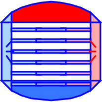
modelDynamicCondenser
Dynamic Cavity
Information
## Copyright © EDF 2002 - 2026
## ThermoSysPro Version 4.2
This component model is documented in Sect. 9.5.4 of the ThermoSysPro book.
# Dynamic condenser
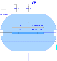
In the condenser, the cooling water flows inside the tube bundle, while the steam and condensate flow inside the cavity.
This model completes the [simple dynamic condenser](modelica://ThermoSysPro.WaterSteam.HeatExchangers.SimpleDynamicCondenser) for it features the thermal exchanges between the fluid in the cavity and the cooling fluid flowing through the tube bundle.
## Modelica component model
The equations mentioned below are implemented in the component *DynamicCondenser*, located in the *WaterSteam.HeatExchangers* sub-library.
This component has 6 connectors:
- C1vap: high-pressure vapor inlet,
- C2vap: low-pressure vapor inlet,
- C1: extra water inlet,
- Ce1: cooling water inlet,
- Ce2: cooling water outlet,
- C2ex: condensed water extraction outlet.
The component is an assembly of a [(monophasic) tube bundle](modelica://ThermoSysPro.WaterSteam.HeatExchangers.DynamicTwoPhaseFlowPipe), a [heat exchanger wall](modelica://ThermoSysPro.Thermal.HeatTransfer.HeatExchangerWall), and a [two-phase cavity](modelica://ThermoSysPro.WaterSteam.Volumes.TwoPhaseCavity) sub-components.

## Nomenclature
See [simple dynamic condenser](modelica://ThermoSysPro.WaterSteam.HeatExchangers.SimpleDynamicCondenser) .
## Governing equations
See [simple dynamic condenser](modelica://ThermoSysPro.WaterSteam.HeatExchangers.SimpleDynamicCondenser) .
## References
El Hefni, Baligh and Bouskela, Daniel (2019). [Modeling and Simulation of Thermal Power Plants with ThermoSysPro](https://link.springer.com/book/10.1007/978-3-030-05105-1), sect. 9.5.4. Springer Nature Switzerland AG.
Revisions
Author

Baligh El Hefni