modelDynamicWaterHeating
Dynamic water heater
Information
## Copyright © EDF 2002 - 2026
## ThermoSysPro Version 4.2
This component model is documented in Sect. 9.5.2 of the ThermoSysPro book.
# Dynamic water heating
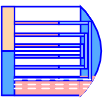
The dynamic water heater is a two-phase shell-and-tube heat exchanger: in the shell, there is vapor and condensate.
As the [static water heater](modelica://ThermoSysPro.WaterSteam.HeatExchangers.NTUWaterHeating), there are two distinct areas in the water heater: the desuperheating and condensation zone, located in the upper part, and the sub-cooled zone, in the lower part.
In the desuperheating zone, the superheated steam flows into the heater and exchanges heat with the liquid flowing through the tube bundle. When the superheated steam becomes saturated steam, it enters the condensation zone.
In the condensation zone, the saturated steam turns into liquid water that enters the subcooled zone.
In the subcooled zone, the liquid inside the cavity keeps exchanging heat with the liquid flowing through the tubes.
## Modelica component model
The equations mentioned below are implemented in the component *DynamicWaterHeating*, located in the *WaterSteam.HeatExchangers* sub-library.
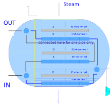
This component has 5 connectors:
- C1vap: vapor inlet,
- C1: extra water inlet,
- Ce1: cooling water inlet,
- Ce2: cooling water outlet,
- C2ex: condensed water extraction outlet.
The component is an assembly of three [(monophasic) tube bundles](modelica://ThermoSysPro.WaterSteam.HeatExchangers.DynamicTwoPhaseFlowPipe), three [heat exchanger walls](modelica://ThermoSysPro.Thermal.HeatTransfer.HeatExchangerWall), a [two-phase cavity](modelica://ThermoSysPro.WaterSteam.Volumes.TwoPhaseCavity) and three Volume sub-components.

## Nomenclature
See [static water heater](modelica://ThermoSysPro.WaterSteam.HeatExchangers.NTUWaterHeating).
## Governing equations
See [static water heater](modelica://ThermoSysPro.WaterSteam.HeatExchangers.NTUWaterHeating).
## References
El Hefni, Baligh and Bouskela, Daniel (2019). [Modeling and Simulation of Thermal Power Plants with ThermoSysPro](https://link.springer.com/book/10.1007/978-3-030-05105-1), sect. 9.5.2. Springer Nature Switzerland AG.
Parameters
| Type | Name | Default | Description |
|---|
| Real | Vf0 | 0.066 | Fraction of initial liquid volume in the Cavity (0 < Vf0 < 1) |
| Units.SI.Pressure | P0c | 1e5 | INitial pressure in the Cavity |
| Units.SI.Radius | Rv | 1.0 | Radius of the Cavity cross-sectional area |
| Units.SI.Length | L1 | 12.5 | Length of drowned pipes in liquid (pipes 1) |
| Units.SI.Length | L2 | 12.5 | Length of Pipe 2 (in steam) |
| Units.SI.Length | L3 | 25 | Length of Pipe 3 (in steam) |
| Units.SI.Length | Lc | 2.5 | support plate spacing in cooling zone(Chicanes) |
| Units.SI.Diameter | Dc | 0.016 | Internal diameter of the cooling pipes |
| Units.SI.Thickness | ec | 2.e-3 | Thickness of the cooling pipes |
| Units.SI.Diameter | DIc | 1.390 | Internal calendre diameter |
| Units.SI.Length | PasL | 0.03 | Longitudinal step or Length bottom pipes triangular step |
| Units.SI.Length | PasT | 0.03 | Transverse step or pipes step |
| Integer | Ns | 10 | Number of segments for one tube pass (half U pipe |
| Integer | ntubes1 | 500 | Numbers of the pipes drowned in water for pipes 1 (drowned pipes in liquid) |
| Integer | ntubes2 | 500 | Numbers of the pipes immersed in steam = NbTub2, for pipes 2 |
| Integer | ntubes3 | 500 | Numbers of the pipes immersed in steam for pipes 3 |
| Integer | ntubesV | 15 | Numbers of pipes in a vertical row (tube bank) |
| Units.SI.SpecificHeatCapacity | cp | 460 | Specific heat capacity of the metal of the cooling pipes |
| Units.SI.Density | rho | 7900 | Density of the metal of the cooling pipes |
| Units.SI.ThermalConductivity | lambda | 26 | Wall thermal conductivity of the cooling pipes |
| Real | DpfCorr | 1.00 | Corrective term for friction pressure loss (dpf) in node i |
| Real | COP0v | 1.0 | Corrective term for Heat exchange coefficient or Fouling coefficient steam side |
| Real | COP0l | 1 | Corrective term for Heat exchange coefficient or Fouling coefficient liquid side |
Revisions
Author

Baligh El Hefni