modelSimpleDynamicCondenser
Information
## Copyright © EDF 2002 - 2026
## ThermoSysPro Version 4.2
This component model is documented in Sect. 9.5.3 of the ThermoSysPro book.
# Simple dynamic condenser
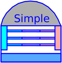
The condenser is a large shell-and-tube heat exchanger composed of a bundle of circular tubes mounted in a cavity.
Steam flows in the cavity and cooling water flows inside the tubes.
Steam in the cavity turns to water due to the thermal exchange with the tube bundle.
External cooling water is pumped through the tube bundles to evacuate the condensation heat of the steam.
The condensate at the outlet is pumped and sent into the feed
water heaters.
The condenser is modeled as a cavity containing a tube bundle with the following assumptions:
- The efficiency of the condenser is equal to 1 (100% of the mass flow rate of input steam is condensed).
- The energy accumulation in pipes is neglected.
- Pressure losses in the cavity are not taken into account.
- The liquid and steam phases are assumed in pressure equilibrium, but not necessarily in thermal equilibrium.
- The pressure at the bottom of the cavity only depends on the liquid level.
## Modelica component model
The equations mentioned below are implemented in the component *SimpleDynamicCondenser*, located in the *WaterSteam.HeatExchangers* sub-library.
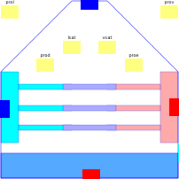
This component has 5 connectors:
- Cv: vapor inlet,
- Cl: liquid outlet,
- Cee: external cooling water inlet,
- Cse: external cooling water outlet,
- yNiveau: water level output.

## Nomenclature
| Symbol| Description| Unit| Definition| Modelica name |
| :----------------------------------- | :----------------------------------------------------------------------------------------------------------------- | :------------------------------------------- | :------------------------------------------- | :----------- |
| \\(A\_{\mathrm{vl}}\\)| Heat exchange surface between vapor and liquid in the cavity| \\(\mathrm{m}^{2}\\)|| Avl |
| \\(A\_{\mathrm{t}}\\)| Internal cross section of the pipes of the tube bundle \(cooling fluid\)| \\(\mathrm{m}^{2}\\)| \\(N\_{\mathrm{t}} \cdot \pi \cdot D^{2} / 4\\) | At |
| \\(C\_{\text {cond }}\\)| Condensation rate inside the cavity| \\(\mathrm{s}^{-1}\\)|| Ccond |
| \\(C\_{\text {evap }}\\)| Evaporation rate inside the cavity| \\(\mathrm{s}^{-1}\\)|| Cevap |
| \\(D\\)| Internal diameter of one pipe of the tube bundle| \\(\mathrm{m}\\)|| D |
| \\(g\\)| Acceleration due to gravity| \\(\mathrm{m} / \mathrm{s}^{2}\\)|| g |
| \\(h\_{\mathrm{c}, \mathrm{i}}\\)| Cooling fluid specific enthalpy at the inlet of the tube bundle| \\(\mathrm{J} / \mathrm{kg}\\)|| Cee.h |
| \\(h\_{\mathrm{c}, \mathrm{o}}\\)| Cooling fluid specific enthalpy at the outlet of the tube bundle| \\(\mathrm{J} / \mathrm{kg}\\)|| Cse.h |
| \\(h\_{l}\\)| Liquid specific enthalpy in the cavity| \\(\mathrm{J} / \mathrm{kg}\\)|| hl |
| \\(h\_{l,0}\\)| Liquid specific enthalpy at the cavity outlet| \\(\mathrm{J} / \mathrm{kg}\\)|| Cl.h |
| \\(h\_{l}^{\text {sat }}\\)| Liquid saturation enthalpy in the cavity| \\(\mathrm{J} / \mathrm{kg}\\)|| lsat.h |
| \\(h\_{\mathrm{v}}\\)| Steam specific enthalpy in the cavity| \\(\mathrm{J} / \mathrm{kg}\\)|| hv |
| \\(h\_{\mathrm{v}, \mathrm{i}}\\)| Steam specific enthalpy at the cavity inlet| \\(\mathrm{J} / \mathrm{kg}\\)|| Cv.h |
| \\(h\_{\mathrm{v}}^{\text {sat }}\\)| Steam saturation enthalpy in the cavity| \\(\mathrm{J} / \mathrm{kg}\\)|| vsat.h |
| \\(K\_{\mathrm{vl}}\\)| Convective heat exchange coefficient between liquid and steam in the cavity| \\(\mathrm{W} / \mathrm{m}^{2} / \mathrm{K}\\) || Kvl |
| \\(L\\)| Tube bundle length \(cooling fluid\)||| L |
| \\(\dot{m}\_{\mathrm{c}}\\)| Cooling fluid \(water\) mass flow rate inside the tube bundle| \\(\mathrm{m}\\)|| Cee.Q, Cse.Q |
| \\(\dot{m}\_{\text {cond }}\\)| Condensation mass flow rate inside the cavity| \\(\mathrm{kg} / \mathrm{s}\\)|| Qcond |
| \\(\dot{m}\_{\text {evap }}\\)| Evaporation mass flow rate inside the cavity| \\(\mathrm{kg} / \mathrm{s}\\)|| Qevap |
| \\(\dot{m}\_{l,0}\\)| Mass flow rate of outgoing condensate| \\(\mathrm{kg} / \mathrm{s}\\)|| Cl.Q |
| \\(\dot{m}\_{\mathrm{v}, \mathrm{i}}\\) | Mass flow rate of incoming vapor| \\(\mathrm{kg} / \mathrm{s}\\)|| Cv.Q |
| \\(N\_{\mathrm{t}}\\)| Number of parallel pipes of the tube bundle| \\(-\\)|| ntubes |
| \\(P\\)| Fluid pressure in the cavity| \\(\mathrm{Pa}\\)|| P |
| \\(P\_{\mathrm{b}}\\)| Fluid pressure at the bottom of the cavity| \\(\mathrm{Pa}\\)| \\(P + \rho\_{l} \cdot g \cdot z\_{l}\\)| Pfond |
| \\(P\_{\mathrm{c}, \mathrm{i}}\\)| Pressure of the cooling fluid at the inlet of the tube bundle| \\(\mathrm{Pa}\\)|| Cee.P |
| \\(P\_{\mathrm{c}, \mathrm{o}}\\)| Pressure of the cooling fluid at the outlet of the tube bundle| \\(\mathrm{Pa}\\)|| Cse.P |
| \\(T\_{l}\\)| Liquid temperature in the cavity| \\(\mathrm{K}\\)|| Tl |
| \\(T\_{\mathrm{v}}\\)| Steam temperature in the cavity| \\(\mathrm{K}\\)|| Tv |
| \\(V\\)| Volume of the cavity| \\(\mathrm{m}^{3}\\)| \\(V\_{l}+V\_{\mathrm{v}}\\)| V |
| \\(V\_{l}\\)| Volume of the liquid in the cavity| \\(\mathrm{m}^{3}\\)| \\(A\_{\mathrm{vl}} \cdot z\_{l}\\)| Vl |
| \\(V\_{\mathrm{v}}\\)| Volume of the steam in the cavity| \\(\mathrm{m}^{3}\\)|| Vv |
| \\(W\_{\text {out }}\\)| Power exchanged between the steam in the cavity and the cooling fluid in the tube bundle| \\(\mathrm{W}\\)|| Wout |
| \\(W\_{\mathrm{vl}}\\)| Power exchanged between the vapor and the liquid phases in the cavity| \\(\mathrm{W}\\)|| Wvl |
| \\(x\_{l}\\)| Vapor mass fraction in the liquid phase inside the cavity| \\(-\\)|| xl |
| \\(x\_{\mathrm{v}}\\)| Vapor mass fraction in the vapor phase inside the cavity| \\(-\\)|| xv |
| \\(X\_{\mathrm{lo}}\\)| Vapor mass fraction in the liquid phase from which the bubbles in the liquid phase start to leave the liquid phase | \\(-\\)|| Xlo |
| \\(X\_{\mathrm{vo}}\\)| Vapor mass fraction in the gas phase from which the droplets in the vaporphase start to leave the vapor phase| \\(-\\)|| Xvo |
| \\(z\_{l}\\)| Liquid level in the cavity| \\(\mathrm{m}\\)| \\(V\_{l} / A\_{\mathrm{vl}}\\)| - |
| \\(z\_{l}\\)| Inlet altitude of the pipes of the tube bundle \(cooling fluid\)| \\(\mathrm{m}\\)|| z1 |
| \\(z\_{2}\\)| Outlet altitude of the pipes of the tube bundle \(cooling fluid\)| \\(\mathrm{m}\\)|| z2 |
| \\(\Delta P\_{\mathrm{f}}\\)| Friction pressure loss for the cooling fluid between the inlet and outlet of the tube bundle| Pa|| dpf |
| \\(\Delta P\_{g}\\)| Pressure loss due to gravity for the cooling fluid between the inlet and outlet of the tube bundle| \\(\mathrm{Pa}\\)|| dpg |
| \\(\Lambda\\)| Friction pressure loss coefficient for the cooling fluid| \\(-\\)|| khi |
| \\(\rho\_{\mathrm{c}}\\)| Cooling fluid density| \\(\mathrm{kg} / \mathrm{m}^{3}\\)|| rhom |
| \\(\rho\_{l}\\)| Liquid density in the cavity| \\(\mathrm{kg} / \mathrm{m}^{3}\\)|| rhol |
| \\(\rho\_{\mathrm{v}}\\)| Steam density in the cavity| \\(\mathrm{kg} / \mathrm{m}^{3}\\)|| rhov |
## Governing equations
### Dynamic mass balance equation for the liquid phase
- Validity domain:
\\(\forall \dot{m}\\) and \\(0<V\_{l}<V\\)
- Mathematical formulation:
$$\rho\_{l} \cdot \frac{\mathrm{d} V\_{l}}{\mathrm{d} t}+V\_{l} \cdot\left[\left\(\frac{\partial \rho\_{l}}{\partial P}\right\)\_{h} \cdot \frac{\mathrm{d} P}{\mathrm{d} t}+\left\(\frac{\partial \rho\_{l}}{\partial h\_{l}}\right\)\_{P} \cdot \frac{\mathrm{d} h\_{l}}{\mathrm{d} t}\right]$$ $$=\dot{m}\_{\text {cond }}-\dot{m}\_{\text {evap }}-\dot{m}\_{l,0}$$
- Comments:
This equation establishes the mass balance between the outgoing liquid, the condensation, and the evaporation flows.
The evaporation flow term should be zero during normal operation of the condenser.
Liquid and steam are assumed at the same pressure \\(P\\).
### Dynamic mass balance equation for the steam phase
- Validity domain:
\\(\forall \dot{m}\\) and \\(0<V\_{\mathrm{v}}<V\\)
- Mathematical formulation:
$$\rho\_{\mathrm{v}} \cdot \frac{\mathrm{d} V\_{\mathrm{v}}}{\mathrm{d} t}+V\_{\mathrm{v}} \cdot\left[\left\(\frac{\partial \rho\_{\mathrm{v}}}{\partial P}\right\)\_{h} \cdot \frac{\mathrm{d} P}{\mathrm{d} t}+\left\(\frac{\partial \rho\_{\mathrm{v}}}{\partial h\_{\mathrm{v}}}\right\)\_{P} \cdot \frac{\mathrm{d} h\_{\mathrm{v}}}{\mathrm{d} t}\right]$$ $$=\dot{m}\_{\mathrm{v}, \mathrm{i}}+\dot{m}\_{\text {evap }}-\dot{m}\_{\text {cond }}$$
- Comments:
This equation establishes the mass balance between the outgoing liquid, the condensation, and the evaporation flows.
The evaporation flow term should be zero during normal operation of the condenser.
### Dynamic energy balance equation for the liquid phase
- Validity domain:
\\(\forall \dot{m}\\) and \\(0<V\_{l}<V\\)
- Mathematical formulation:
$$V\_{l} \cdot\left[\left\(\frac{P}{\rho\_{l}} \cdot\left\(\frac{\partial \rho\_{l}}{\partial P}\right\)\_{h}-1\right\) \cdot \frac{\mathrm{d} P}{\mathrm{d} t}+\left\(\frac{P}{\rho\_{l}} \cdot\left\(\frac{\partial \rho\_{l}}{\partial h\_{l}}\right\)\_{P}+\rho\_{l}\right\) \cdot \frac{\mathrm{d} h\_{l}}{\mathrm{d} t}\right]$$ $$= \dot{m}\_{\mathrm{cond}} \cdot\left[h\_{l}^{\mathrm{sat}}-\left\(h\_{l}-\frac{P}{\rho\_{l}}\right\)\right]-\dot{m}\_{\mathrm{evap}} \cdot\left[h\_{\mathrm{v}}^{\mathrm{sat}}-\left\(h\_{l}-\frac{P}{\rho\_{l}}\right\)\right]$$ $$- \dot{m}\_{l, \mathrm{o}} \cdot\left[h\_{l, \mathrm{o}}-\left\(h\_{l}-\frac{P}{\rho\_{l}}\right\)\right]+W\_{\mathrm{vl}}$$
- Comments:
This equation establishes the mass balance between the outgoing liquid, the condensation, and the evaporation flows.
The evaporation flow term should be zero during normal operation of the condenser.
### Dynamic energy balance equation for the steam phase
- Validity domain:
\\(\forall \dot{m}\\) and \\(0<V\_{\mathrm{v}}<V\\)
- Mathematical formulation:
$$V\_{\mathrm{v}} \cdot\left[\left\(\frac{P}{\rho\_{\mathrm{v}}} \cdot\left\(\frac{\partial \rho\_{\mathrm{v}}}{\partial P}\right\)\_{h}-1\right\) \cdot \frac{\mathrm{d} P}{\mathrm{d} t}+\left\(\frac{P}{\rho\_{\mathrm{v}}} \cdot\left\(\frac{\partial \rho\_{\mathrm{v}}}{\partial h\_{\mathrm{v}}}\right\)\_{P}+\rho\_{\mathrm{v}}\right\) \cdot \frac{\mathrm{d} h\_{\mathrm{v}}}{\mathrm{d} t}\right]$$ $$=-\dot{m}\_{\mathrm{cond}} \cdot\left[h\_{l}^{\mathrm{sat}}-\left\(h\_{\mathrm{v}}-\frac{P}{\rho\_{\mathrm{v}}}\right\)\right]-W\_{\mathrm{vl}}+W\_{\mathrm{out}}$$
- Comments:
### Power exchanged by convection between the two phases inside the cavity
- Validity domain:
\\(\forall T\_{l}\\) and \\(\forall T\_{\mathrm{v}}\\)
- Mathematical formulation
$$W\_{\mathrm{v} 1}=K\_{\mathrm{Vl}} \cdot A\_{\mathrm{vl}} \cdot\left\(T\_{\mathrm{v}}-T\_{l}\right\)$$
- Comments:
### Power exchanged between the cavity and the pipe bundle
- Validity domain:
\\(\forall \dot{m}\_{\mathrm{c}}\\) and \\(\forall \dot{m}\_{\mathrm{v}}\\)
- Mathematical formulation:
$$W\_{\text {out }}=\dot{m}\_{\mathrm{v}, \mathrm{i}} \cdot\left\(h\_{\mathrm{v}, \mathrm{i}}-h\_{\mathrm{l}}\right\)=\dot{m}\_{\mathrm{c}} \cdot\left\(h\_{\mathrm{c}, \mathrm{i}}-h\_{\mathrm{c}, \mathrm{o}}\right\)$$
- Comments:
All the steam power is transfered to the cooling fluid.
### Momentum balance equation for the cold fluid
- Validity domain:
\\(\forall \dot{m}\_{\mathrm{c}}\\)
- Mathematical formulation:
$$P\_{\mathrm{c}, \mathrm{i}}-P\_{\mathrm{c}, \mathrm{o}}=\Delta P\_{\mathrm{f}}+\Delta P\_{\mathrm{g}}$$ $$\Delta P\_{\mathrm{f}}=\frac{\Lambda \cdot \dot{m}\_{\mathrm{c}} \cdot \lvert \dot{m}\_{\mathrm{c}}\rvert}{2 \cdot A\_{\mathrm{t}}^{2} \cdot \rho\_{\mathrm{c}}}$$ $$\Delta P\_{\mathrm{g}}=\rho\_{\mathrm{c}} \cdot g \cdot\left(z\_{2}-z\_{l}\right)$$
- Comments:
The purpose of this equation is to compute the mass flow rate of the cooling fluid.
## References
El Hefni, Baligh and Bouskela, Daniel (2019). [Modeling and Simulation of Thermal Power Plants with ThermoSysPro](https://link.springer.com/book/10.1007/978-3-030-05105-1), sect. 9.5.3. Springer Nature Switzerland AG.
Parameters
| Type | Name | Default | Description |
|---|
| Units.SI.Volume | V | 1 | Cavity volume |
| Units.SI.Area | A | 1 | Cavity cross-sectional area |
| Real | Vf0 | 0.5 | Fraction of initial water volume in the drum (active if steady_state=false) |
| Units.SI.AbsolutePressure | P0 | 0.1e5 | Fluid initial pressure (active if steady_state=false) |
| Boolean | gravity_pressure | false | true: fluid pressure at the bottom of the cavity includes gravity term - false: without gravity term |
| Real | Ccond | 0.01 | Condensation coefficient |
| Real | Cevap | 0.09 | Evaporation coefficient |
| Real | Xlo | 0.0025 | Vapor mass fraction in the liquid phase from which the liquid starts to evaporate |
| Real | Xvo | 0.9975 | Vapor mass fraction in the gas phase from which the liquid starts to condensate |
| Units.SI.Area | Avl | A | Heat exchange surface between the liquid and gas phases |
| Real | Kvl | 1000 | Heat exchange coefficient between the liquid and gas phases |
| Units.SI.Length | L | 10. | Pipe length |
| Units.SI.Diameter | D | 0.02 | Pipe internal diameter |
| Units.SI.Length | e | 2.e-3 | Wall thickness |
| Units.SI.Position | z1 | 0 | Inlet altitude |
| Units.SI.Position | z2 | 0 | Outlet altitude |
| Units.SI.Length | rugosrel | 0.0007 | Pipe roughness |
| Real | lambda | 0.03 | Friction pressure loss coefficient (active if lambda_fixed=true) |
| Integer | ntubes | 1 | Number of pipes in parallel |
| Units.SI.Area | At | ntubes*pi*D^2/4 | Internal pipe cross-section area (cooling fluid) |
| Boolean | steady_state | true | true: start from steady state - false: start from (P0, Vl0) |
| Integer | mode | 0 | IF97 region. 1:liquid - 2:steam - 4:saturation line - 0:automatic |
| Boolean | continuous_flow_reversal | false | true: continuous flow reversal - false: discontinuous flow reversal |
Revisions
Author

Baligh El Hefni