modelPump_dp_tau_centrifugal_DesignPoint
Extends from Modelica.Icons.Example.
Information
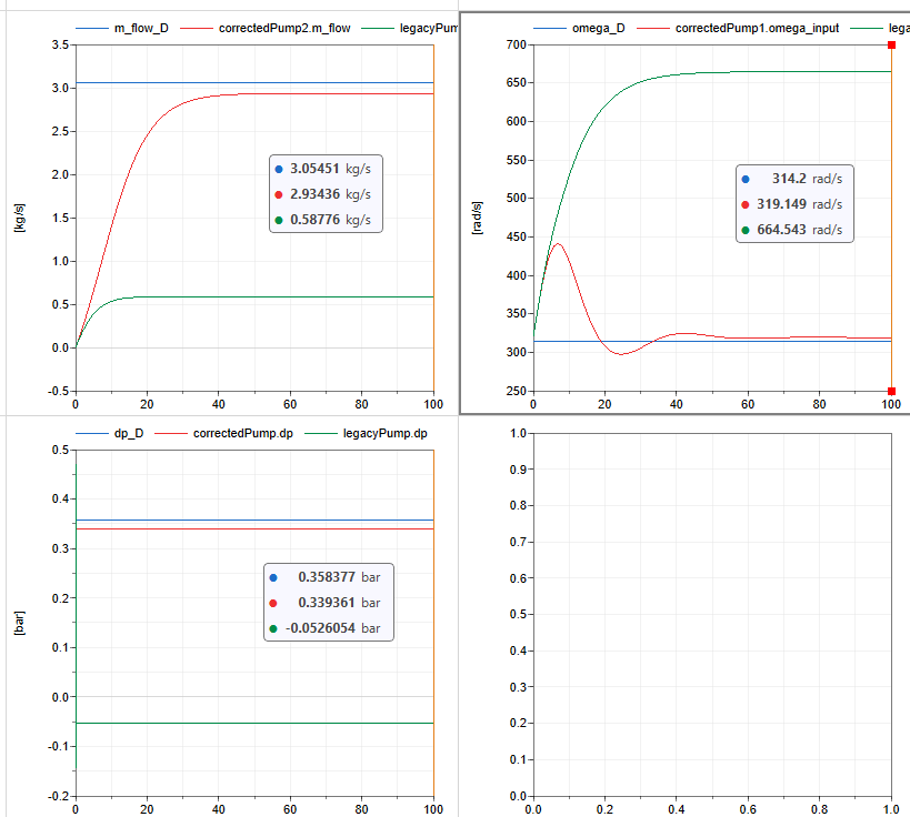
Test model for the design point of the pump characteristics according to dp_tau_centrifugal :
- flow at design head and design rotational speed (top left)
- head at design flow and design rotational speed (bottom left)
- rotational speed at design flow and design head (top right)
The model compares the legacy formulation
(useLegacyReynolds = true) with the corrected formulation
(useLegacyReynolds = false).
Only the stationary solution is of interest. Transient behavior is introduced by the controllers solely to drive the system to the correct stationary operating point.
The legacy version does not reproduce the specified design point. The corrected version is much closer to the specified design point, but still shows a small offset of about 5 %. This remaining deviation is caused by viscosity effects that are not compensated at the design point. An initial attempt to compensate these effects was only able to slightly reduce the offset.
Parameters
| Type | Name | Default | Description |
|---|---|---|---|
| SI.Pressure | p_in | 100000 | Inlet pressure |
| SI.Temperature | T_in | 293.15 | Inlet temperature |
| SI.Density | rho_in | Medium.density_pT(p_in, T_in) | Inlet density |
| SI.Height | TDH_D | 3.6610 | Design pressure head (max efficiency) |
| SI.VolumeFlowRate | V_flow_D | 3.06e-3 | Design volume flow (max efficiency) |
| SI.AngularVelocity | omega_D | 314.2 | Design angular velocity |
| SI.Pressure | dp_D | TDH_D*rho_in*Modelica.Constants.g_n | Design pressure difference |
| SI.MassFlowRate | m_flow_D | V_flow_D*rho_in | Design mass flow rate |
Components
| Type | Name | Default | Description |
|---|---|---|---|
| ThermofluidStream.Boundaries.Source | source | ||
| ThermofluidStream.Boundaries.Sink | sink | ||
| ThermofluidStream.DropOfCommons | dropOfCommons | ||
| ThermofluidStream.Processes.Pump | correctedPump | ||
| Modelica.Blocks.Sources.Constant | rotationalSpeed | ||
| Modelica.Blocks.Sources.Constant | massFlowRate | ||
| Modelica.Blocks.Math.Feedback | feedback | ||
| Modelica.Blocks.Continuous.PI | PI | ||
| ThermofluidStream.Sensors.SingleFlowSensor | flowSensor | ||
| Boundaries.Source | source1 | ||
| Boundaries.Sink | sink1 | ||
| ThermofluidStream.Processes.Pump | correctedPump1 | ||
| Modelica.Blocks.Math.Feedback | feedback1 | ||
| Modelica.Blocks.Continuous.PI | PI1 | ||
| Sensors.SingleFlowSensor | flowSensor1 | ||
| Modelica.Blocks.Sources.Constant | massFlowRate1 | ||
| FlowControl.CheckValve | checkValve | ||
| Boundaries.Source | source2 | ||
| Boundaries.Sink | sink2 | ||
| ThermofluidStream.Processes.Pump | legacyPump | ||
| Modelica.Blocks.Math.Feedback | feedback2 | ||
| Modelica.Blocks.Continuous.PI | PI2 | ||
| Sensors.SingleFlowSensor | flowSensor2 | ||
| Boundaries.Source | source3 | ||
| Boundaries.Sink | sink3 | ||
| ThermofluidStream.Processes.Pump | legacyPump1 | ||
| Sensors.SingleFlowSensor | flowSensor3 | ||
| FlowControl.CheckValve | checkValve1 | ||
| Modelica.Blocks.Continuous.PI | PI3 | ||
| Modelica.Blocks.Math.Feedback | feedback3 | ||
| Boundaries.Source | source4 | ||
| Boundaries.Sink | sink4 | ||
| ThermofluidStream.Processes.Pump | correctedPump2 | ||
| Boundaries.Source | source5 | ||
| Boundaries.Sink | sink5 | ||
| ThermofluidStream.Processes.Pump | legacyPump2 | ||
| Modelica.Blocks.Sources.Constant | rotationalSpeed1 |
Contents
| Name | Description |
|---|---|
| Medium |
Revisions
-
2026, by Raphael Gebhart (raphael.gebhart@dlr.de):
Initial version.