
modelPhysicalPL_L4
Extends from TransiEnt.Components.Gas.VolumesValvesFittings.Base.PressureLoss_L4_extICom (VLE || PL Base Class with extended iCom).
Information
1. Purpose of model
This model is a physical pressure loss model, which can also model disturbances.
2. Level of detail, physical effects considered, and physical insight
The model considers the actual pressure loss of a one-phase fluid in a pipe in the turbulent regime. The calculation of the Darcy friction factor has been copied from Modelica.Fluid.Dissipation.PressureLoss.StraightPipe.dp_turbulent_MFLOW since it is numerically more efficient to integrate the equations directly in the model and it gives more insight.
Viscosity can be chosen to be constant or a correlation can be used.
Linearization can be used to achieve better numerical efficiency and stability.
numberOfMFlowNoDist is used to apply disturbances at the indices of m_flow. From t_dist_start until t_dist_end the corresponding mass flow rates are set to zero.
3. Limits of validity
This model is only valid in the turbulent regime. The linearization should be adjusted according to the application.
4. Interfaces
(none)
5. Nomenclature
(no elements)
6. Governing Equations
The correlation for the viscosity is:
![eta = coeff_visc[1]+ coeff_visc[2]*p+ coeff_visc[3]*T+ sum(coeff_visc[4:end]*xi)](resources/TransiEnt/Resources/Images/equations/equation-3gmGOo3T.png) with T=T_const
with T=T_const
The pressure loss can be calculated according to [1]:

which can be transformed into

which can be simplified to
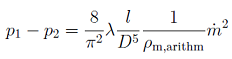
using the arithmetic mean of the density of inlet and outlet of each control volume. For the Reynolds number also the arithmetic mean of the viscosity is used.
7. Remarks for Usage
The default viscosity correlation coefficients for natural gas have been curve fitted for pressures of 1,10,20...100 bar, temperatures of 5,10,15 °C for the compositions of natural gas "Russland", "Verbundgas", "Nordsee I" and "Nordsee II" from [1] p.51 and hydrogen shares of 0,10...100 mole-% with a goodness of fit of 0.8013. The usual viscosity changes in natural gas pipelines have no big impact on the pressure loss so a linear correlation should be sufficient. The same was done for methane-hydrogen mixtures.
For pure hydrogen, the default setting is that another correlation for pure hydrogen is used which was determinded for pressures of 1,10,20...100 bar and temperatures of 5,10,15 °C with a goodness of fit of 0.9958.
8. Validation
The model has been validated against the compressible pressure loss calculation.
9. References
[1] G. Cerbe, B. Lendt, K. Brüggemann, M. Dehli, F. Gröschl, K. Heikrodt, T. Kleiber, J. Kuck, J. Mischner, T. Schmidt, A. Seemann, and W. Thielen, Grundlagen der Gastechnik. Gasbeschaffung - Gasverteilung - Gasverwendung, 8th ed. München: Carl Hanser Verlag, 2017.
10. Version History
Model created by Carsten Bode (c.bode@tuhh.de), Sep 2019
Modified by Carsten Bode (c.bode@tuhh.de), Aug 2020 (viscosity correlation, more exact calculation, elimination of FluidDissipation function)
Modified by Robert Flesch (flesch@xrg-simulation.de), Sep 2020 (linearization, new iCom)
Modified by Carsten Bode (c.bode@tuhh.de), Apr 2021 (added disturbance)
Parameters
| Type | Name | Default | Description |
|---|---|---|---|
| Boolean | frictionAtInlet (from PressureLoss_L4_extICom) | ||
| Boolean | frictionAtOutlet (from PressureLoss_L4_extICom) | ||
| Boolean | useHomotopy (from PressureLoss_L4_extICom) | ||
| SI.MassFlowRate | m_flow_nom (from PressureLoss_L4_extICom) | iCom.m_flow_nom | Nominal mass flow rate |
| SI.PressureDifference | Delta_p_nom (from PressureLoss_L4_extICom) | iCom.Delta_p_nom | Nominal pressure loss wrt. all parallel tubes |
| Integer | loopStart | if frictionAtInlet then 1 else 2 | First index of loop |
| Integer | loopEnd | if frictionAtOutlet then iCom.N_cv + 1 else iCom.N_cv | Last index of loop |
| Integer | loopIdx | loopStart:loopEnd | All loop indices |
| Integer | notLoopIdx | if frictionAtInlet and frictionAtOutlet then fill(1, 0) elseif frictionAtInlet and not frictionAtOutlet then {iCom.N_cv + 1} elseif not frictionAtInlet and frictionAtOutlet then {1} else {1, iCom.N_cv + 1} | All indices that do not appear in the loop |
| Modelica.Units.SI.Length | d_hyd | geo.diameter_hyd[1] | Hydraulic diameter |
| Real | kD | k/d_hyd | Relative roughness |
| Modelica.Units.SI.Area | A_cross | Modelica.Constants.pi*d_hyd^2/4 | Circular cross sectional area |
| Modelica.Units.SI.Length[geo.N_cv + 1] | Li | if not frictionAtInlet and not frictionAtOutlet then geo.Delta_x_FM*geo.length/(geo.length - geo.Delta_x_FM[1] - geo.Delta_x_FM[iCom.N_cv + 1]) elseif not frictionAtInlet and frictionAtOutlet then geo.Delta_x_FM*geo.length/(geo.length - geo.Delta_x_FM[1]) elseif frictionAtInlet and not frictionAtOutlet then geo.Delta_x_FM*geo.length/(geo.length - geo.Delta_x_FM[iCom.N_cv + 1]) else geo.Delta_x_FM | Length |
| Integer[:] | numberOfMFlowNoDist | if numberOfMFlowDist[1] == 0 then 1:iCom.N_cv + 1 else findSetDifference(1:iCom.N_cv + 1, numberOfMFlowDist) | numbers of mass flows which will be undisturbed |
| Fundamental Definitions | |||
| Modelica.Units.SI.Height | k | simCenter.roughnessGasPipes | Absolute roughness |
| Real | MIN | Modelica.Constants.eps | Limiter |
| Real | factor | 1 | Factor to modify pressure loss |
| Modelica.Units.SI.PressureDifference | dp_switch | 1000 | Pressure difference at which function is linearized |
| Modelica.Fluid.Dissipation.Utilities.Types.Roughness | roughness | Modelica.Fluid.Dissipation.Utilities.Types.Roughness.Considered | |
| Viscosity | |||
| Boolean | useViscCorr | false | true if viscosity correlation shall be used, false for constant viscosity |
| Real[iCom.mediumModel.nc - 1 + 3] | coeff_visc | if iCom.mediumModel.nc == 1 then {2.77160904091864e-06, 1.37797594879264e-14, 2.05004849130428e-08} elseif iCom.mediumModel.nc == 2 then {3.49826606827002e-07, 1.04303247526047e-13, 2.71567407127824e-08, 2.80651000814681e-06} else {-1.43911039529083e-05, 3.75699281723867e-13, 1.96789492178842e-08, 1.89714979419216e-05, 2.93055875111180e-05, -1.78595469221118e-06, -1.29406293799004e-05, 1.02682267821617e-05, 4.15851977756051e-05} | Coefficients for viscosity calculation (1st for constant part, 2nd for pressure, 3rd for temperature, rest for n-1 composition entries (vector must have nine entries, no matter how many components the gas consists of; the remaining entries will be ignored)) |
| Modelica.Units.SI.Temperature | T_const | simCenter.T_ground | Constant temperature for viscosity calculation |
| Modelica.Units.SI.Pressure | p_nom | iCom.p_nom | Nominal pressure for viscosity calculation |
| Modelica.Units.SI.MassFraction[iCom.mediumModel.nc - 1] | xi_nom | iCom.xi_nom | Nominal composition for viscosity calculation |
| Modelica.Units.SI.DynamicViscosity | eta_const | coeff_visc[1] + coeff_visc[2]*p_nom + coeff_visc[3]*T_const + sum({coeff_visc[3 + j]*xi_nom for j in 1:iCom.mediumModel.nc - 1}) | Constant dynamic viscosity |
| Disturbance | |||
| Integer[:] | numberOfMFlowDist | {0} | 0 for no disturbance, otherwise give number (1...N_cv+1) |
| Modelica.Units.SI.Time | t_dist_start | 1e10 | Start time of disturbance |
| Modelica.Units.SI.Time | t_dist_end | t_dist_start + 1 | End time of disturbance |
Components
| Type | Name | Default | Description |
|---|---|---|---|
| TransiEnt.Components.Gas.VolumesValvesFittings.Base.IComVLE_L3_OnePort_extended | iCom (from PressureLoss_L4_extICom) | ||
| ClaRa.Basics.ControlVolumes.Fundamentals.Geometry.PipeGeometry_N_cv | geo (from PressureLoss_L4_extICom) | ||
| SI.PressureDifference[geo.N_cv + 1] | Delta_p (from PressureLoss_L4_extICom) | Pressure difference | |
| SI.MassFlowRate[geo.N_cv + 1] | m_flow (from PressureLoss_L4_extICom) | ||
| TransiEnt.SimCenter | simCenter | ||
| Modelica.Units.SI.Density[iCom.N_cv + 1] | rho | Density | |
| Modelica.Units.SI.DynamicViscosity[iCom.N_cv + 1] | eta | Dynamic Viscosity | |
| Modelica.Units.SI.MassFlowRate[iCom.N_cv + 1] | m_flow_1 | Mass flow rate in one tube | |
| Modelica.Fluid.Dissipation.Utilities.Types.DarcyFrictionFactor[iCom.N_cv + 1] | lambda_FRI_calc_switch | Adapted Darcy friction factor | |
| SI.ReynoldsNumber[iCom.N_cv + 1] | Re_switch | Reynolds number assuming turbulent regime | |
| SI.MassFlowRate[iCom.N_cv + 1] | m_flow_switch | ||
| Modelica.Fluid.Dissipation.Utilities.Types.DarcyFrictionFactor[iCom.N_cv + 1] | lambda_FRI_calc | Adapted Darcy friction factor | |
| SI.ReynoldsNumber[iCom.N_cv + 1] | Re_turb | Reynolds number assuming turbulent regime | |
| SI.Velocity[iCom.N_cv + 1] | velocity | Mean velocity | |
| Real[iCom.N_cv + 1] | m_flow_rel_dist | Relative mass flow due to the disturbance, 1 if no disturbance, 0 if disturbance |
Contents
| Name | Description |
|---|---|
| TYP1 |