classTutorial
Electric Drives Tutorial
Extends from Modelica.Icons.Information (Icon for general information packages).
Information
Tutorial - Defining a new electric motor model
The following process will demonstrate how to create a new electric motor model using these interface definitions. This tutorial will guide you through building a simple DC electric motor.
- Create a new model that extends
VehicleInterfaces.ElectricDrives.Interfaces.BaseDCMachine,
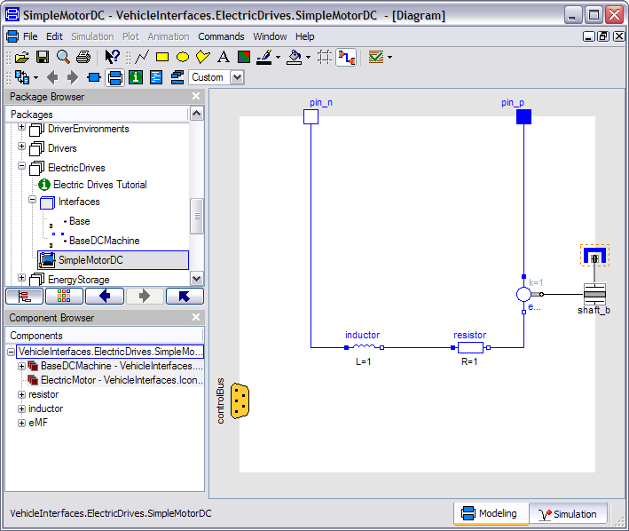
it should look like this:
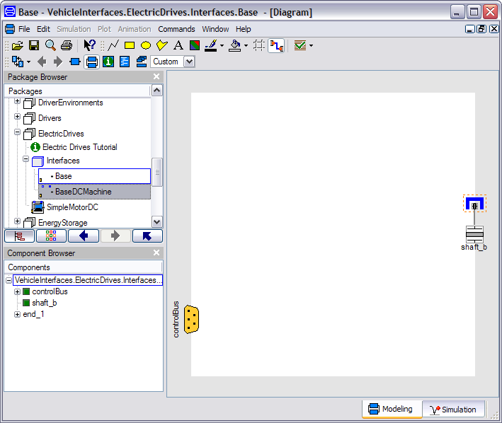
- In the component browser, right click on BaseDCMachine
and select Parameters from the context menu to produce
the following parameter dialog
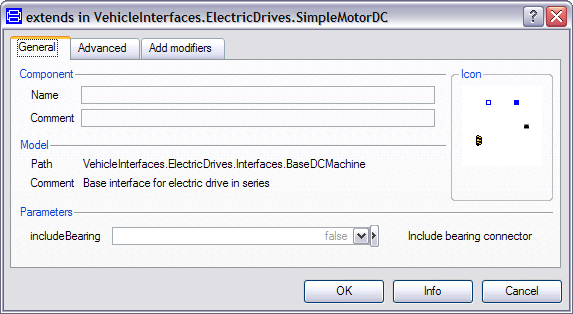
- This dialog allows you to enable/disable the optional connections by setting includeBearing as required for your new motor model. The shaft_b connector is of the type Modelica.Mechanics.MultiBody.Interfaces.FlangeWithBearing, the parameter includeBearing controls whether the bearing connector within the shaft_b connector is enabled or not.
- You can now define your driveline model as required
Creating a simple electric motor example
The following steps demonstrate how to create a simple rear-wheel drive driveline model. The driveline model will transmit the torque from the transmission to the rear wheels via a propshaft, differential with final drive and then two halfshafts. No torque reaction in to the transmission housings will be modelled.
Starting from step 3 above.
- First, decide if the bearing connector is required in the model and set the internal parameter appropriately.
- Add the following blocks and connections to the diagram.