
modelPowerAngle
Generator at fixed power angle
Extends from Modelica.Icons.Example (Icon for runnable examples).
Information
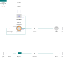
This example is a first step on the way 'from voltage source to generator model'.
Lower part of example (for comparison with and interpretation of upper part):
simplest generator description as a "voltage behind reactance".
Upper part: 3-winding generator model, isotrope with x_d = x_q.
The power-angle is artificially fixed. The correspondence is:
  Vgen1.alpha0 ~ powerAngle.delta
  Vgen1.v0     ~ exciter.v_f
In both cases the terminal voltage is fixed by the bus voltage. The results should coincide.
See for example:
sensor.p[1:2] active and reactive power
Components
| Type | Name | Default | Description |
|---|---|---|---|
| PowerSystems.System | system | ||
| PowerSystems.AC3ph.Machines.Control.PowerAngle | powerAngle | ||
| PowerSystems.Control.Exciters.ExciterSimple | exciter | ||
| PowerSystems.AC3ph.Machines.Control.Excitation | excitation | ||
| PowerSystems.AC3ph.Machines.Synchron3rd_ee | generator | ||
| PowerSystems.AC3ph.Sensors.Psensor | sensor | ||
| PowerSystems.AC3ph.Sources.InfBus | infBus | ||
| PowerSystems.AC3ph.Sources.Voltage | Vgen1 | ||
| PowerSystems.AC3ph.Impedances.Inductor | RLgen1 | ||
| PowerSystems.AC3ph.Sensors.Psensor | sensor1 | ||
| PowerSystems.AC3ph.Sources.Voltage | Vbus1 | ||
| PowerSystems.AC3ph.Nodes.GroundOne | grd1 | ||
| PowerSystems.AC3ph.Nodes.GroundOne | grd2 | ||
| PowerSystems.AC3ph.Nodes.GroundOne | grd3 | ||
| PowerSystems.Common.Thermal.BdCondV | bdCond |