
modelTieLine
Generators and power-oscillations
Extends from Modelica.Icons.Example (Icon for runnable examples).
Information
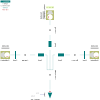
Tie line with three generators (third as infinite slack bus), feeding a variable load. The load changes abruptly at t=2 and induces power oscillations between the nodes.
The oscillations are slowly damped (depending on control), but may also lead to system instability.
After the load decreases, system frequency starts to increase from 60 to 62 Hz with an intermediate maximum of 63 Hz. For narrow frequency-bounds 'system.f_lim', for example {58, 62} simulation stops when the limit is reached (after 5 sec).
See for example:
 sensor's.p[1:2]    active and reactive power
 system.omega       system frequency
Components
| Type | Name | Default | Description |
|---|---|---|---|
| PowerSystems.System | system | ||
| PowerSystems.AC3ph.Generation.TurboGenerator | turboGen1 | ||
| PowerSystems.AC3ph.Nodes.BusBar | bus1 | ||
| PowerSystems.AC3ph.Sensors.Psensor | sensor1 | ||
| PowerSystems.AC3ph.Lines.RXline | line1 | ||
| PowerSystems.AC3ph.Generation.TurboGenerator | turboGen2 | ||
| PowerSystems.AC3ph.Nodes.BusBar | bus2 | ||
| PowerSystems.AC3ph.Sensors.Psensor | sensor2 | ||
| PowerSystems.AC3ph.Lines.RXline | line2 | ||
| PowerSystems.AC3ph.Generation.TurboGenerator | turboGen3 | ||
| PowerSystems.AC3ph.Sensors.Psensor | sensor3 | ||
| PowerSystems.AC3ph.Lines.RXline | line3 | ||
| PowerSystems.AC3ph.Sensors.Psensor | sensorLoad | ||
| PowerSystems.AC3ph.Loads.Zload | load | ||
| PowerSystems.Blocks.Signals.Transient | pq_change | ||
| PowerSystems.Control.Setpoints.Set_w_p_v | setpts1 | ||
| PowerSystems.Control.Setpoints.Set_w_p_v | setpts2 | ||
| PowerSystems.Control.Setpoints.Set_w_p_v | setpts3 | ||
| PowerSystems.Common.Thermal.BdCondV | bdCond1 | ||
| PowerSystems.Common.Thermal.BdCondV | bdCond2 | ||
| PowerSystems.Common.Thermal.BdCondV | bdCond3 |