
modelCISEPlant
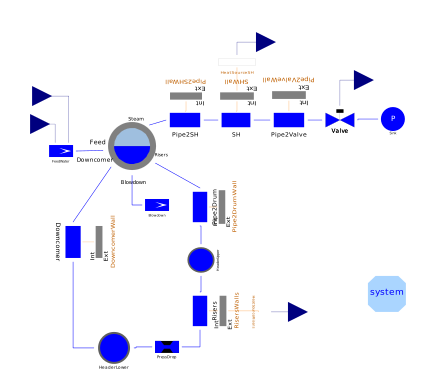
Model of the CISE lab steam generator
Information
This is the model of the CISE steam generation plant described in the paper: F. Casella, A. Leva, "Modelica open library for power plant simulation: design and experimental validation", Proceedings of the 2003 Modelica Conference, Linkö eping, Sweden, 2003.
The geometric parameters are already set. The start values set in the model parameters are guess values around the nominal full load steady state (60 bar drum pressure).
This model cannot be simulated alone, as the boundary conditions (feedwater flowrate and enthalpy, steam valve opening, power to the risers and power to the superheater) are not set. See the CiseSim model instead.
Connectors
| Type | Name | Default | Description |
|---|---|---|---|
| Modelica.Blocks.Interfaces.RealOutput | DrumPressure | ||
| Modelica.Blocks.Interfaces.RealOutput | DrumLevel | ||
| Modelica.Blocks.Interfaces.RealInput | FeedWaterFlow | ||
| Modelica.Blocks.Interfaces.RealInput | RiserPower | ||
| Modelica.Blocks.Interfaces.RealInput | ValveOpening | ||
| Modelica.Blocks.Interfaces.RealInput | SHPower | ||
| Modelica.Blocks.Interfaces.RealInput | FeedWaterEnthalpy |
Components
| Type | Name | Default | Description |
|---|---|---|---|
| Water.Drum | Drum | ||
| Water.SourceMassFlow | FeedWater | ||
| Water.Flow1DFV2ph | Downcomer | ||
| Water.Flow1DFV2ph | Risers | ||
| Water.Flow1DFV2ph | Pipe2Drum | ||
| Water.SinkMassFlow | Blowdown | ||
| Water.Flow1DFV | Pipe2SH | ||
| Water.Flow1DFV2ph | SH | ||
| Water.Flow1DFV2ph | Pipe2Valve | ||
| Water.ValveVap | Valve | ||
| Water.SinkPressure | Sink | ||
| Thermal.HeatSource1DFV | HeatSourceSH | ||
| Thermal.HeatSource1DFV | HeatSourceRisers | ||
| Water.Header | HeaderLower | ||
| Water.Header | HeaderUpper | ||
| Thermal.MetalTubeFV | DowncomerWall | ||
| Thermal.MetalTubeFV | RisersWalls | ||
| Thermal.MetalTubeFV | Pipe2DrumWall | ||
| Thermal.MetalTubeFV | Pipe2SHWall | ||
| Thermal.MetalTubeFV | SHWall | ||
| Thermal.MetalTubeFV | Pipe2ValveWall | ||
| Water.PressDrop | PressDrop | ||
| System | system |
Contents
| Name | Description |
|---|---|
 Medium Medium |
Revisions
- 19 Apr 2005
by Francesco
Casella:
Initialization by steady-state initial equations. - 20 Dec 2004
by Francesco
Casella:
New heat transfer components. - 15 Nov 2004
by Francesco
Casella:
Adapted to Modelica.Media. - 3 Nov 2004
by Francesco
Casella:
Input/Output connectors added. - 1 Oct 2003
by Francesco
Casella:
First release.